In a DEM-CFD two-way coupling simulation, the particles are part of the fluid flow and will affect it in a two-way interaction, i.e., the particle movement is affected by the interaction with other particles and the fluid around it while the flow is also affected by the particle presence.
On the Rocky side, the fluid flow will exert forces upon the particle, including pressure gradient (including buoyancy) force, drag force, and virtual mass force (optional). On the CFD side, the reaction of the forces upon the particles will be applied over the fluid phases.
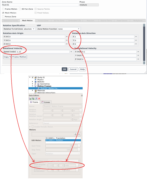
If geometries are shared between the two programs and movement of these geometries are also desired, Moving Meshes can be enabled for the geometry on the Fluent side and those settings will be automatically converted into a Rocky Motion Frame upon importing the CAS file (Figure 8.1: Motion settings in Fluent (top) are automatically converted into a new Motion Frame in Rocky (bottom).). In this way, a consistent motion for the shared geometry can be achieved between the two programs.
Figure 8.1: Motion settings in Fluent (top) are automatically converted into a new Motion Frame in Rocky (bottom).
The scheme used in the Rocky DEM-CFD two-way coupling allows both solvers to run in parallel, which can considerably decrease simulation time if the solvers do not compete for resources. During setup within the Rocky coupling interface, you can control the number of processors required by each solver to avoid resource competition. Also, since Rocky can make use of GPU and Multi-GPU processing, an alternative to increasing the coupling performance is to set the CFD solver to run on CPU cores and set Rocky to run on the GPU cards.
CFD COUPLING SETTINGS: MOVE CFD CELLS WITH ROCKY BOUNDARIES
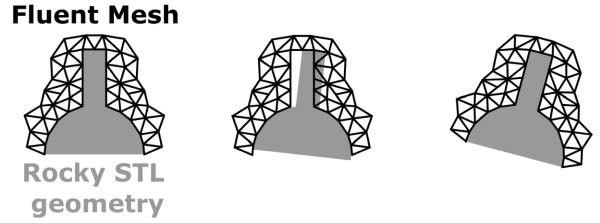
Considering a 2-way CFD coupled simulation where there are moving meshes in Fluent. By default, the geometries in Rocky and in Fluent are not syncronized in between CFD timesteps. Thus, while Rocky is marching towards the next timestep and the geometry is being updated, the particles may end up leaving the CFD domain, causing the fluid-particle interactions to vanish, mass fluxes on the walls, velocity oscillations, etc.
An usual way to mitigate this issue is by lowering the CFD timestep, but that is computationally costly. The Move CFD Cells (Beta) module uses the motion properties to rotate the fluid meshes inside Rocky so that both CFD domain boundaries and Rocky boundaries are always syncronized, allowing the use of greater CFD timesteps.