


| Applicable Products: | Ansys Multiphysics, Ansys Mechanical |
| Level of Difficulty: | Moderate |
| Interactive Time Required: | 60 to 90 minutes |
| Discipline: | Thermal |
| Analysis Type: | Nonlinear transient |
| Element Types Used: | PLANE55 |
| Features Demonstrated: | Conduction, convection, phase change, selecting, solution control, time-history postprocessing, use of a "get function" |
| Help Resources: | Transient Thermal Analysis and PLANE55 |
This is a transient heat-transfer analysis of a casting process. The solidification process occurs over a duration of four hours. The casting is made in an L-shaped sand mold with four-inch-thick walls. Convection occurs between the sand mold and the ambient air.
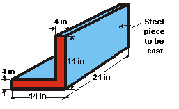
Objective: Track the temperature distribution in the steel casting and mold during solidification.
| Material Properties for Sand | |
| Conductivity (KXX) | 0.025 Btu/(hr-in-oF) |
| Density (DENS) | 0.054 lb/in3 |
| Specific heat (C) | 0.28 Btu/(lb-oF) |
| Conductivity (KXX) for Steel | |
| at 0oF | 1.44 Btu/(hr-in-oF) |
| at 2643oF | 1.54 |
| at 2750oF | 1.22 |
| at 2875oF | 1.22 |
| Enthalpy (ENTH) for Steel | |
| at 0oF | 0.0 Btu/in3 |
| at 2643oF | 128.1 |
| at 2750oF | 163.8 |
| at 2875oF | 174.2 |
| Initial Conditions | |
| Temperature of steel | 2875 oF |
| Temperature of sand | 80 oF |
| Convection Properties | |
| Film coefficient | 0.014 Btu/(hr-in2-oF) |
| Ambient temperature | 80 oF |
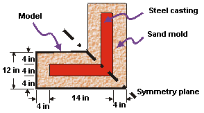
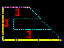
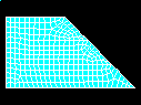
You will perform a 2D analysis of a one unit thick slice. Half-symmetry is used to reduce the size of the model. The lower half is the portion to be modeled.
The mold material (sand) has constant material properties. The casting (steel) has temperature-dependent thermal conductivity and enthalpy; both are input in a table of values versus temperature. The enthalpy property table captures the latent heat capacity of the metal as it solidifies. Radiation effects are ignored.
Solution control is used to establish several nonlinear options, including automatic time stepping. Automatic time stepping determines the proper time step increments needed to converge the phase change nonlinearity. This means that smaller time step sizes will be used during the transition from molten metal to solid state.
Use the information in the problem description and the steps below as a guideline in solving the problem on your own. Or, use the detailed interactive step-by-step solution by selecting the link for step 1.
Prepare for a Thermal Analysis
Input Geometry
2. Read in the geometry of the casting.
Define Materials
3. Define material properties.
4. Plot material properties vs. temperature.
Generate Mesh
Apply Loads
7. Apply convection loads on the exposed boundary lines.
Obtain Solution
10. Specify initial conditions for the transient.
11. Set time, time step size, and related parameters.
13. Solve.
Review Results
14. Enter the time-history postprocessor and define variables.
15. Plot temperature vs. time.
To Set Preferences:
(check) "Individual discipline(s) to show in the GUI" = Thermal
[OK]
Reading in the file containing the casting model.
File name: casting.inp (Click the link to download the file in .zip format.)
[OK]

Define the sand mold material properties as material number 1. These are not functions of temperature.
(double-click) "Thermal", then "Conductivity", then "Isotropic"
"KXX" = 0.025
[OK]
(double-click) "Specific Heat"
"C" = 0.28
[OK]
(double-click) "Density"
"DENS" = 0.54
[OK]
The metal casting is defined as material number 2. These properties change significantly as the metal cools down from the liquid phase to the solid phase. They are therefore entered in a table of properties versus temperature.
First define the temperature-dependent thermal conductivity.
"Define Material ID" = 2
[OK]
(double-click) "Isotropic"
[Add Temperature] three times to create fields for the four temperatures.
"T1" = 0
"T2" = 2643
"T3" = 2750
"T4" = 2875
"KXX" at "T1" = 1.44
"KXX" at "T2" = 1.54
"KXX" at "T3" = 1.22
"KXX" at "T4" = 1.22
Copy the four temperatures so that you can paste them into the Enthalpy dialog box.
Select the temperatures by holding the left mouse button and dragging across the temperature row so that the row is highlighted.
Ctrl+C to copy the temperatures.
[OK]
Define the temperature dependent enthalpy.
(double-click) "Enthalpy"
[Add Temperature] three times to create fields for the four temperatures.
Paste the temperatures into the dialog box by highlighting the T1 temperature field, and pressing Ctrl+V.
"ENTH" at "T1" = 0
"ENTH" at "T2" = 128.1
"ENTH" at "T3" = 163.8
"ENTH" at "T4" = 174.2
[OK]
(double-click) "Thermal conduct. (iso)" under Material Model Number 2.
[Graph]
[OK]
(double-click) "Enthalpy" under the right or left window.
[Graph]
[OK]
Toolbar: SAVE_DB
Define the element type as PLANE55.
[Add ...]
"Thermal Solid" (left column)
"Quad 4node 55" (right column)
[OK]
[Close]
Toolbar: SAVE_DB

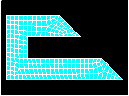
Specify a SmartSize of 4. This will allow a slightly finer mesh than the default.
(check) "Smart Size"
(slide) "Fine Course" = 4
[Mesh]
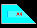
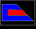
Mesh the mold area first. Note that the material attribute reference number defaults to 1 and there is no need to set attributes before meshing the area.
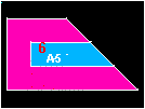
Pick the mold area A5. (Hint: Place the mouse cursor on top of the A5 label when you pick—this is the picking "hot spot," based on the centroid of the area.)
[OK]
Before meshing the casting area, set the material attribute to that of steel (material 2).
(drop down in MeshTool) "Element Attributes" = Global, then [Set]
(drop down) "Material number" = 2
[OK]
[Mesh] in MeshTool
Pick area A4

[OK]
[Close] in MeshTool

Note: The mesh you obtain may vary slightly from the mesh shown here. As a result of this, you may see slightly different results during postprocessing. For a discussion of results accuracy, see Planning Your Approach in the Modeling and Meshing Guide.
To verify that the elements have the right materials, plot them with different colors for different materials.
(drop down) "Elem / Attrib numbering" = Material numbers
[OK]
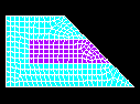
Note: the elements of material 1 form the sand mold. The elements of material 2 form the steel casting. You can also plot the elements showing materials in different colors without displaying the associated material numbers.
(drop down) "Numbering shown with" = Colors only
[OK]
Toolbar: SAVE_DB
Apply the convection to the lines of the solid model. Loads applied to solid modeling entities are automatically transferred to the finite element model during solution.
Pick the three lines that are exposed to ambient air.
[OK]
"Film coefficient" = 0.014
"Bulk temperature" = 80
[OK]
Toolbar: SAVE_DB
(check) "Type of analysis" = Transient
[OK]
(check) "Solution method" = Full
[OK]
The Approach and Assumptions section of this tutorial mentioned that solution control is used to establish several nonlinear options. In this step, you will be directed to the online help for solution control so you can examine the details of this feature.
You will access this help topic by clicking on the Help button from within the Nonlinear Solution Control dialog box.
Note that solution control is on by default.
Before clicking on the Help button in the next step, you should be aware that the help information may appear in the same window as this tutorial, replacing the contents of the tutorial. If this is the case, after reading the help information, you will need to click on the Back button to return to this tutorial. If the help information appears in a separatewindow from the tutorial, you can minimize or close the help window after you read the help information.
[Help] then read the details on Solution Control.
If the help information replaced the tutorial, click on the Back button to return to the tutorial. If the help information appears in a separate window, you can close or minimize that window.
[Cancel] to remove the dialog box.
The mold is initially at an ambient temperature of 80oF and the molten metal is at 2875oF. Use select entities to obtain the correct set of nodes on which to apply the initial temperatures. First select the casting area, then select the nodes within that area and apply the initial molten temperature to those nodes. Next, invert the selected set of nodes and apply the ambient temperature to the mold nodes.
Start by plotting areas.
(first drop down) "Areas"
[OK]
Pick area A4, which is the casting.
[OK]

[Pick All] to use selected nodes.
(drop down) "DOF to be specified" = TEMP
"Initial value of DOF" = 2875
[OK]
(first drop down) "Nodes"
(second drop down) "Attached to"
(check) "Areas, all"
[Invert] This is an action command; the selected set of nodes is immediately inverted.
[Cancel] to close the dialog box.
[Pick All] to use all selected nodes.
"Initial value of DOF" = 80
[OK]
Always select Everything again after you have finished selecting the nodes.
Toolbar: SAVE_DB
Stepped boundary conditions simulate the sudden contact of molten metal at 2875 oF with the mold at ambient temperature. The program selects automatic time stepping, enabling the time-step size to be modified depending on the severity of nonlinearities in the system. (For example, the program uses smaller time steps during the phase change.) The maximum and minimum time-step sizes represent the limits for this automated procedure.
"Time at end of load step" = 4
This setting represents 4 hours.
"Time step size" = 0.01
(check) "Stepped or ramped b. c." = Stepped
"Minimum time step size" = 0.001
"Maximum time step size" = 0.25
[OK]
(check) "File write frequency" = Every substep
[OK]
Toolbar: SAVE_DB
Review the information in the status window, then select (Windows), or (Linux), to close the window.
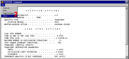
[OK] to initiate the solution.
[Close] when the solution is done.
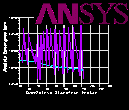
While Mechanical APDL solves the analysis, the Graphical Solution Tracking (GST) monitor plots the "Absolute Convergence Norm" as a function of the "Cumulative Iteration Number." Notice that the solution is assumed to have converged for values less than or equal to the convergence criteria.
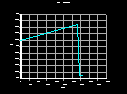
Use the time-history postprocessor to look at the variation of temperature with respect to time at one point on the casting (on the symmetry plane).
(check) "Node numbers" = On
(drop down) "Numbers shown with" = Colors & numbers
[OK]
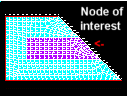
The node at the center of the casting on the symmetry plane is the node of interest. Use a "get function" to define a variable equal to the value of the node number at the location of interest (16,6,0). By using a variable to identify the node at the center point, the analysis will be more flexible in that the center node will always be used even if the mesh, and therefore node numbers, change.
"Selection"=cntr_pt = node (16,6,0)
[Accept}
Note the center point node number. This number can vary due to differences in the mesh.
[Close]
[+] to add data.
(double-click) "Nodal Solution", then "DOF Solution", then "Temperature"
"Variable Name" = center
[OK]
Type cntr_pt in the picker, then press Enter.
[OK] in the picker.
"1st variable to graph" = 2
[OK] to plot the results at cntr_point as a function of time.
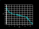
Notice that the solidification region is approximately 2643oF - 2750oF. Your graph may vary slightly.
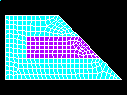
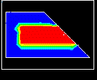
Animate the solidification of the molten metal. To better visualize the solidification process, specify three contours. One will represent the molten metal (T greater than 2750 oF), one will represent the solidified metal (T less than 2643 oF), and the third will represent everything in between.
To generate an animation, enter the General Postprocessor and read the first set of results.
(check) "Node numbers" = Off
(drop down) "Elem / Attrib numbering" = No numbering
(drop down) "Replot upon OK/Apply?" = Do not replot
[OK]
As indicated in the brackets at the upper left corner of the dialog box, the command to specify non_uniform contours is /CVAL.
"V1" = 2643
"V2" = 2750
"V3" = 3000
The three values represent the upper bounds of the first, second, and third contours, respectively.
[OK]
Procedure on all systems:
"Number of animation frames" = 30
(check) "Auto contour scaling" = Off
[OK]
During the animation, notice the three separate colors - red for temperatures greater than 2750 oF (molten steel), green for temperatures between 2643 oF and 2750 oF (the "mushy" phase-change region), and blue for temperatures below 2643 oF (the solidified steel and the sand mold). As you would expect, the last region to solidify is the material at the center of the casting. (Remember that a symmetry model was used.)
Make selections in the Animation Controller (not shown), if necessary, then [Close].
To visualize the temperature distribution throughout the model over the 4 hour span, animate the temperature distribution with the default contour settings. To change the contour settings back to their default value, enter /CVAL in the Input Window. (Alternatively, you can go back to the Non_Uniform Contours window and set all values to zero.)
Type /CVAL, then press Enter.
[OK]
Make selections in the Animation Controller (not shown), if necessary, then [Close].