


The purpose of these tutorials is to introduce you to the extensive analysis capabilities of Mechanical APDL.
Running the tutorials online while running Mechanical APDL requires that you make the best use of your monitor's display area. With just minor adjustments to the browser and the Mechanical APDL interface, you can read a tutorial's instructions on one side of your screen, and perform the instructions in Mechanical APDL on the other.
Following is an example layout captured on a 21-inch monitor. It is a typical representation of how a display appears while running a tutorial using the Windows version of Mechanical APDL.
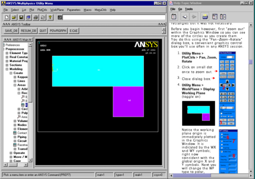
The tutorial window containing the tabs was removed by clicking the Undock button (large button located furthest to the right), then minimizing the tabbed window.
The tutorial window is moved to the right side of the screen, and the Mechanical APDL window is reduced horizontally to accommodate the tutorial window. Use this layout as an example and adjust your own display, based on the size of your monitor.
If a Mechanical APDL dialog box appears on top of either a tutorial or the Mechanical APDL window, move it anywhere on the screen by dragging the window header.
Each tutorial begins with a problem description that includes approaches and assumptions. A summary of the tasks required to complete the tutorial is provided.
A task contain the specific actions needed to complete the task. Example tasks include "Add areas," "Define material properties," "Mesh the area," and "Plot the deformed shape." A typical tutorial requires approximately 20 tasks, with the number varying according to analysis complexity.
For each task, individually numbered actions guide you through the task.
A menu path is typically one of the first action within a task. An example of a menu path action is:
A menu path represents the complete location of a particular function in the Graphical User Interface (GUI). The first part of the path (Main Menu) determines where the function is found. It is usually either the Main Menu or the Utility Menu. Go to that region to perform the function. The remaining part of the path lists the menu topics that you select with the mouse.
Actions presented after a menu path either guide you through completing a dialog box, or show you how to pick graphical locations.
For completing a dialog box, some actions are followed by a red arrow
( ) indicating that a small picture of
the dialog box is available if you scroll to the right. The picture includes
large red numbers, each referencing the corresponding action. (The numbers are
positioned in the dialog box at the locations where you are to perform the
actions (button, box, drop-down list, etc.). )
) indicating that a small picture of
the dialog box is available if you scroll to the right. The picture includes
large red numbers, each referencing the corresponding action. (The numbers are
positioned in the dialog box at the locations where you are to perform the
actions (button, box, drop-down list, etc.). )
Task actions in several of the tutorials adhere to the following conventions:
Items that you need to fill in reproduce the wording in the dialog boxes and are in quotes, followed by an equal sign, then the value you should enter. Example:
3. "Load VOLT Value" = 5 Button labels are in brackets. Example:
4. [Pick All] Actions, locations, or any other items that may not be obvious are enclosed in parentheses before or after GUI wording in quotes. Examples:
2. (double-click) "Structural" 5. (drop down) "Action" 7. "Scaler Tet 98" (right column)
Some task actions instruct you to pick specific entities on a graphic. An example of the convention is shown:
| 6. Pick lines 17 and 8 |
Here, red numbers are displayed on the picture at the locations where you are to pick. The red number is a cross-reference to the action.
Specify a jobname for each tutorial analysis. The jobname helps to identify files generated by Mechanical APDL that are related to a specific analysis. When starting Mechanical APDL, you can specify the jobname in the launcher. While working in Mechanical APDL, you can change the jobname by selecting:
then typing the jobname, and selecting OK.
When applicable, you will be instructed to set preferences for the tutorial analysis. Setting a preference for a given engineering discipline instructs Mechanical APDL to display only those menu options that apply to the specified discipline. (If you do not set preferences, menu options for all disciplines appear, but non-applicable options are dimmed based on the element types used in the model.)
Set preferences at or near the beginning of an analysis. (Most of the tutorials include this step before the model is meshed.) You can set a preference by selecting:
then checking the box associated with the desired engineering discipline, and selecting OK.
Try running Structural Tutorial first, even if you typically run analyses in other engineering disciplines. The Structural tutorial is documented extensively, includes graphics of all dialog boxes used, and introduces you to Mechanical APDL terminology used in other tutorials.
After successfully performing the Structural tutorial, feel free to try any of the others in any order. You can select a problem that demonstrates the Mechanical APDL features in your discipline, but all introductory tutorials demonstrate universal Mechanical APDL analysis techniques in some way. You can learn something from every tutorial.
You can access a tutorial via the Table of Contents or by clicking on the name of the tutorial in the following list: