| Applicable Products: | Ansys Multiphysics, Ansys Mechanical, Ansys Structural |
| Level of Difficulty: | Easy |
| Interactive Time Required: | 30 to 45 minutes |
| Discipline: | Structural |
| Analysis Type: | Modal |
| Element Types Used: | PLANE182, SOLID185 |
| Features Demonstrated: | Extrusion with a mesh, selecting, eigenvalue modal analysis, animation |
| Help Resources: | Modal Analysis, PLANE182 and SOLID185 |
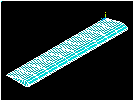
This is a simple modal analysis of a wing of a model airplane. The wing is of uniform configuration along its length and its cross-sectional area is defined to be a straight line and a spline. It is held fixed to the body of the airplane on one end and hangs freely at the other.
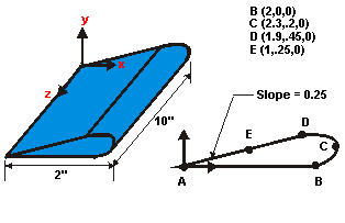
Objective: Find the wing's natural frequencies and mode shapes.
The wing is made of low density polyethylene with a Young's modulus of 38x103 psi, Poisson's ratio of 0.3, and a density of 8.3E-5 lbf-sec2/in4.
Assume that the side of the wing connected to the plane is completely fixed in all degrees of freedom. The wing is solid and material properties are constant and isotropic.
Use solid modeling to generate a 2D model of the cross-section of the wing. Create a reasonable mesh and extrude the cross-section into a 3D solid model (to be meshed automatically).
Use the information in this description and the steps below as a guideline in solving the problem on your own. Or, use the detailed interactive step-by-step solution by choosing the link for step 1.
Input Geometry
1. Read in geometry input file.
Define Materials
3. Define constant material properties.
Generate Mesh
6. Extrude the meshed area into a meshed volume.
Apply Loads
8. Apply constraints to the model.
Obtain Solution
9. Specify analysis types and options.
10. Solve.
Review Results
11. List the natural frequencies.
Read in the file contaning the model.
File name: wing.inp (Click the link to download the file in .zip format.)
[OK]
Set preferences to filter quantities pertaining to this discipline only.
(check) "Structural"
[OK]
Define two element types: a 2D element and a 3D element. Mesh the wing cross-sectional area with 2D elements, then extrude the area to create a 3D volume. The mesh will be extruded along with the geometry so that 3D elements are created in the volume.
[Add...]
"Structural Solid" (left column)
"Quad 4node 182" (right column)
"Structural Solid" (left column)
"Brick 8node 185" (right column)
Choose “Simple Enhanced Str” for the element technology.
[OK]
[CLOSE]
Toolbar: SAVE_DB
Specify mesh controls to obtain the given mesh density.
"Size Controls Global" = [Set]
"Element edge length" = 0.25
[OK]
[Mesh]
[Pick All]
[Close] Warning.

[Close] Meshtool
Toolbar: SAVE_DB
The mesh contains a PLANE182 triangle, resulting in a warning. Alternatively, you can use PLANE183 during the element definitions to avoid the warning.
Your mesh may vary slightly from the mesh shown. As a result, you may see slightly different results during postprocessing. For a discussion of results accuracy, see Planning Your Approach.
Before applying constraints to the fixed end of the wing, deselect all PLANE182 elements used in the 2D area mesh, as they are not used for the analysis.
(first drop down) "Elements"
(second drop down) "By Attributes"
(check) "Elem type num"
"Min,Max,Inc" = 1
(check) "Unselect"
[Apply]
Constraints are applied to all nodes located where the wing is fixed to the body. Select all nodes at z = 0, then apply the displacement constraints.
(first drop down) "Nodes"
(second drop down) "By Location"
(check) "Z coordinates"
"Min,Max" = 0
(check) "From Full"
[Apply]
[Pick All] to pick all selected nodes.
"DOFs to be constrained" = All DOF
[OK] Note that by leaving "Displacement" blank, a default value of zero is used.

Reselect all nodes.
(second drop down) "By Num/Pick"
[Sele All] to immediately select all nodes from entire database.
[Cancel] to close dialog box.
Toolbar: SAVE_DB
Specify a modal analysis type.
(check) "Modal"
[OK]
(check) "Block Lanczos" (Block Lanczos is the default for a modal analysis.)
"No. of modes to extract" = 5
"No. of modes to expand" = 5
[OK]
[OK] All default values are acceptable for this analysis.
Toolbar: SAVE_DB
Review the information in the status window, then choose:
(Windows),
or
(Linux), to close the window.
[OK] to initiate the solution.
[Yes]
[Yes]
Based on previous discussions, the warnings are accepted. Messages appear in the verification window because PLANE182 elements have been defined but not used in the analysis; instead, they were used to mesh a 2D cross-sectional area.
[Close] to acknowledge that the solution is done.
Set the results for the first mode to be animated.
[OK]
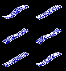
Observe the first mode shape:
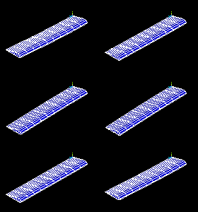
Make selections in the Animation Controller (not shown), if necessary, then choose Close.
Animate the next mode shape.
[OK]
Observe the second mode shape:
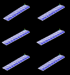
Repeat red steps 4 through 7 above, and view the remaining three modes.
Observe the third mode shape:
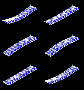
Observe the fourth mode shape:
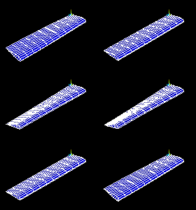
Observe the fifth mode shape:
