


If you have started with an initial 3D tire model and have performed the rim-mounting and tire-inflation analyses on that model, you are ready to perform the the footprint analysis in this load step.
If you have performed the rim-mounting and tire-inflation analyses on a 2D axisymmetric tire model, then created your 3D tire model via a 2D to 3D analysis to transfer the results onto the 3D model, continue the simulation via a multiframe restart to perform the footprint analysis.
The footprint analysis occurs in two load steps:
Move the road surface toward the tire (via a displacement loading on the pilot node of the tire-road contact pair) to establish the contact between them. The rim remains fixed during this load step.
Example 4.6: Establishing Tire-Road Contact
! Continue the simulation after 2D to 3D analysis
/clear,nostart
! Perform a multiframe restart analysis
/solu
antype,,restart,2,      ! Restart after 2D to 3D analysis is completed
allsel,all
cnkmod,12,12,3          ! Convert the tire-rim contact pair to bonded type
time,3
d,2000,all
d,2000,ux,-0.006        ! Move the road surface toward the tire
nlgeom,on
nsub,10,10000,5
outres,all,last
nropt,unsym
rescontrol,,all,last
allsel,all
solve
If the relative deformation between the rim and the tire is not desired in this or subsequent analyses, you can change the behavior of the tire-rim contact pair to a bonded contact pair (if it is not already bonded) (CNKMOD). Exercise caution, however, as nonstandard application of this capability can lead to incorrect results.
You can apply a proportionate vehicle load directly on the tire via the pilot node of the tire-rim contact pair at center, or transfer it to the tire by applying it on the pilot node of the tire-road contact pair as described here.
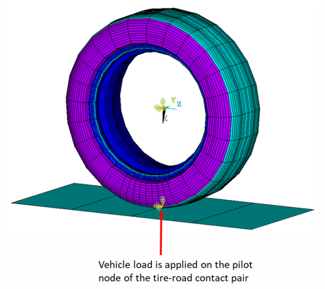
Before transferring a vehicle load to the tire, delete previously applied displacement loading on the pilot node of the tire-road contact pair.
Example 4.7: Applying a Vehicle Load to the 3D Tire Model
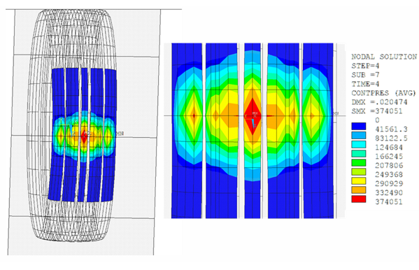
! Apply the vehicle load and solve the footprint analysis
time,4
ddel,2000,ux,,,on  !Delete the previously applied displacement loading
f,2000,fx,-3000    !Apply the vehicle load on the pilot node
allsel,all
nlgeom,on
nsub,10,10000,5
outres,all,last
rescontrol,,all,last
solve
Adding a Non-Zero Camber
If you require a non-zero angle for the tire camber, add it after this load step by applying rotation to either the road or the rim. Ensure that reaction forces are calculated using the correct orientation. For more information, see Camber Analysis.