


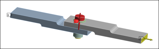
A bolted lap joint between two steel plates is modeled to illustrate bolt self-loosening with different loading conditions. The model includes: two steel plates, an M12 bolt, two washers, and a non-locking nut as shown in the following figure. The model was investigated experimentally by Abad, et al. 2014 [2].
Boundary conditions and loading are as follows:
At surface A, a cyclic displacement is applied.
At surface B, all degrees of freedom are fixed.
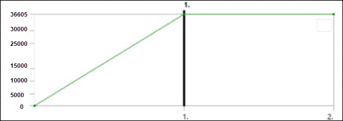
In the first load step, a pretension ramped load is applied at C (F = - 36,605 N) then locked (displacement controlled).
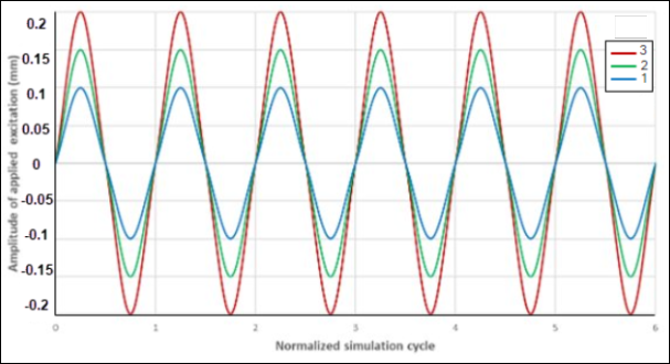
A cyclic displacement is applied at the tip of the upper plate at surface A with three amplitudes (0.10, 0.15 and 0.20 mm) and three frequencies (10,110 and 650 Hz) for each direction of excitation (x, y and z).
The initial clearance between the hole and bolt shank is 0.50 mm.
The bottom of the second plate (B) is fixed in all directions. The problem is simulated for the six-oscillating cycles to estimate bolt self-loosening. The wear is automatically scaled, and six simulation cycles account for the wear that occurs over thousands of physical cycles.
A simplified bolt thread model is used to model the bolt and nut. The cyclic displacement on the top of the plate indenter is applied through a rigid pilot node. The wear is defined in all parts between the bolt head and the nut, and for the sake of simplicity, the same wear and friction coefficient is used. In the simplified bolt thread model, wear is defined for the threaded part as well. For a contact pair, two mating surfaces might have different wear coefficients. Symmetric contact cannot be defined for the simplified bolt model. So, wear may be accounted for on either the bolt thread or the nut thread, but not on both. The resultant axial force on the bolt-nut pair is the pretention load.