


The left surface of the bottom plate, B, is fixed in all directions. At surface A, a cyclic displacement (amplitude 0.1,0.15 and 0.20 mm with three different loading frequencies 10, 110, and 650 Hz) is applied in the X/Y/Z direction, keeping all other degrees of freedom fixed as shown in Figure 71.1: Bolt Self-loosening Model for a Simple Lap Joint The loading is applied in two loading steps. First, the pretention load is applied to the bolt section at C, F = 36,605 N, then oscillatory displacement is applied at surface A. The problem is simulated for six oscillating cycles to estimate bolt self-loosening. The two-flexure mode natural frequencies of the clamped-clamped bolted joint are:

where, λ1/2 have two values 4.73 and 7.85, L = 25 mm is the length between clamped-clamped portion, EI is the flexure rigidity, and M is the mass between clamped portions [4]. The first eight numerically calculated natural frequencies of the clamped assembly are listed below.
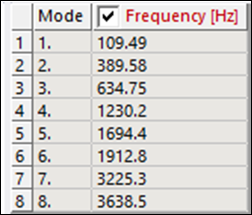
The hand calculated flexural frequencies of the clamped assembly are 659.53 Hz and 1816.56 Hz. The bolt flexure mode matches with the third mode. To see the effect of dynamic loading, the problem is solved at three frequencies (10, 110 and 650 Hz).