

The following topics are available:
This benchmark problem showcases fracture analysis of a surface crack under a bending loading. A finite plate contains a semi-elliptical surface crack at the center of the specimen. The plate is subjected to pure bending at the top and bottoms ends.
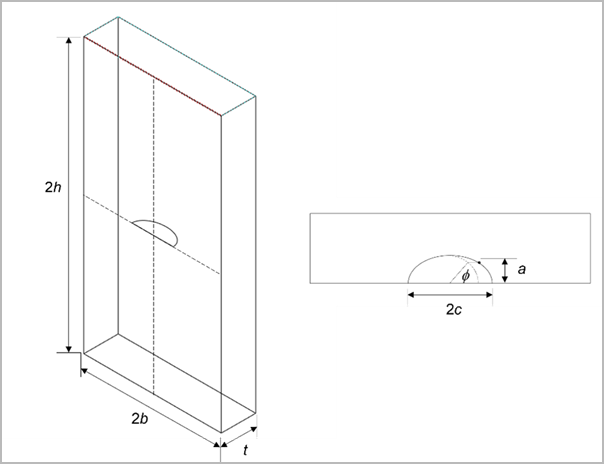
The specimen has the following geometrical parameters:
b = 20 mm, t = 10 mm, h = 5b = 100 mm
Two types of analyses are demonstrated here:
Static crack analysis with the crack-sizes:
(a,c) = (1 mm, 2 mm), (5 mm, 10 mm)
Fatigue crack-growth analysis with the initial crack-size:
(a,c) = (1 mm, 2 mm)
The material is assumed to be isotropic linear-elastic with the following properties:
| Property | Parameter | Value | Unit |
|---|---|---|---|
| Elastic modulus |

| 200 | GPa |
| Poisson's ratio |

| 0.3 | -- |
| Paris’ law constants |

| 10-10 | (mm/cycle) / (MPa - mm0.5)2.1 |

| 2.1 | -- |
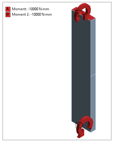
The top and bottom faces of the plate are subjected to bending moment load M, which induce mode-I fracture for the given orientation of the surface crack.
| M = 1000 N.mm |
Rigid body motion in all three directions are properly constrained.
Newman and Raju [7]have proposed an empirical relation for estimating the stress-intensity factor (SIF) for a surface crack under tension and/or bending loadings. The relation is based on fitting to previously obtained finite-element results for different geometries.
For pure bending loading, the SIF is estimated as:
 | (1) |
for  ,
,  ,
,  and
and  .
.
The remote outer-fiber bending stress  is calculated as:
 | (2) |
The function  is given by:
 | (3) |
The function  has the form:
 | (4) |
where
 | (5) |
 | (6) |
 | (7) |
 | (8) |
 | (9) |
 | (10) |
The function  is taken as:
 | (11) |
where
 | (12) |
 | (13) |
 | (14) |
 | (15) |
 | (16) |
For the static crack analysis, stress-intensity factor  result for the moment load M is compared with the empirical solution.
For the fatigue crack-growth analysis, stress ratio  is assumed. As the crack grows, the SIF results for the evolving crack
shape are compared with the corresponding empirical solution.
is assumed. As the crack grows, the SIF results for the evolving crack
shape are compared with the corresponding empirical solution.
| a, c (mm) | ||
| Crack-1 | 1, 2 |
 |
| Crack-2 | 5, 10 |

|
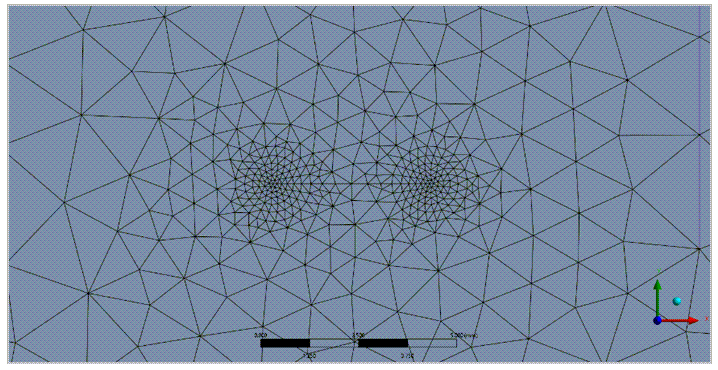
The model is created using the Mechanical application. The geometry is mesh using 10-noded tetrahedron elements (SOLID187). A semi-elliptical crack is added for each analysis using the crack insertion tool.
The element size at the crack-front is around 0.1 mm. The crack-front has 99 nodes. The whole model has around 110k nodes and 76k elements.
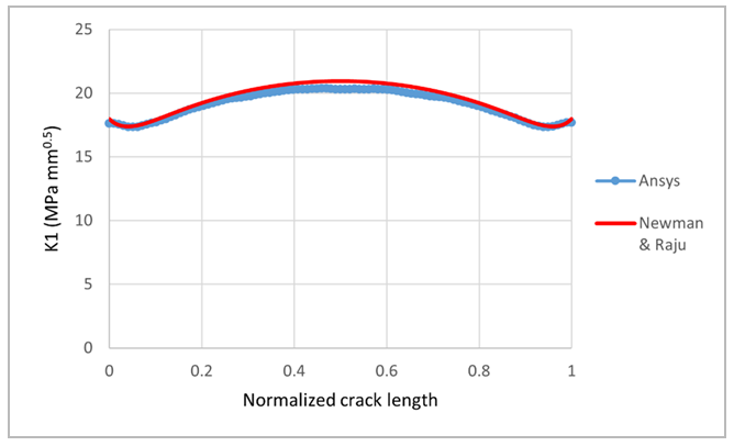
The bending loading induces mode-I fracture. The K1 results are calculated over 6 contours around the crack front, as shown in Figure 24. SIF results for contour-1 (nearest to the crack-front) are generally erroneous due to the inaccurate FE stress solution very close to the crack-front. The other contour results are close and therefore exhibit path-independence of the SIF calculation, using the contour integration method.
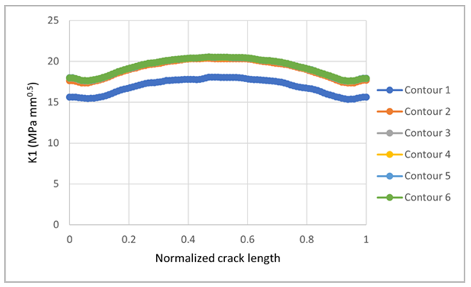
The results are also close to the Newman-Raju empirical results, as shown.
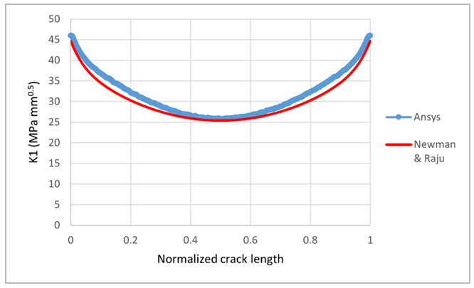
Crack-2 has a larger size than crack-1. The ratio  is selected to compare the SIF results with Newman-Raju relation which
is valid only till this limit of
is selected to compare the SIF results with Newman-Raju relation which
is valid only till this limit of  . The element size at the crack-front is same as in crack-1
(0.1 mm). The crack-front has 483 nodes. The whole model has around 287k nodes and
205k elements.
. The element size at the crack-front is same as in crack-1
(0.1 mm). The crack-front has 483 nodes. The whole model has around 287k nodes and
205k elements.
The SIF results are reasonably close to the empirical solution, as shown.
SMART fatigue crack-growth analysis is performed to evaluate the SIF during crack-growth. The crack is allowed to grow automatically for 30 substeps.
A stress ratio  is assumed. Hence, the SIF range
  at any crack-front node is determined as
  . The crack-growth increment at any substep follows the fatigue law:
 | (17) |
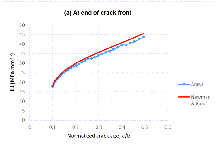
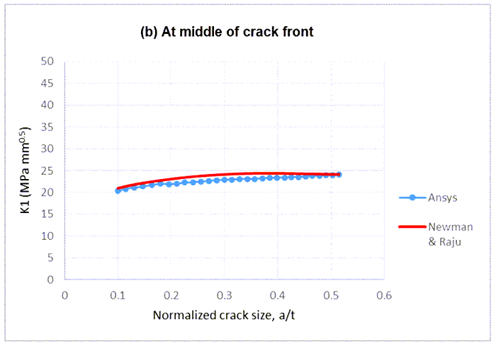
The following figure shows the crack fronts and the corresponding variation of K1 at the first and the last (30th) substeps.
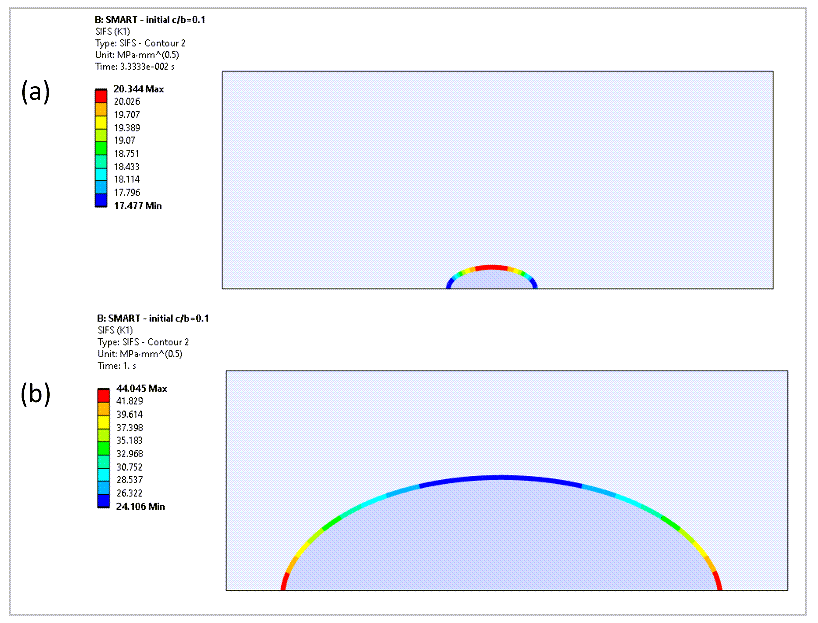
The accumulated crack-growth in 30 substeps at the end and center of the crack front are 7.90 mm and 4.15 mm, respectively. The crack maintains a shape close to semi-ellipse, and thus K1 results can be compared with the Newman-Raju empirical solution at each crack-growth step (Figure 28). The K1 results show a reasonable match with the empirical solution.
The following important observations were made in this study:
The SIF results are path-independent contour-2 onwards.
The reference equation used in the study is an empirical equation, and is not an exact analytical solution. The empirical equation is based on fitting to previously obtained SIF results from 3D FE analyses. The reference paper [7]reports that for
 , the empirical equation is within ±5% of the FE results.
Static crack analysis was performed for 2 crack-sizes. Tetrahedral mesh (SOLID187) is used in the analyses. For the smaller crack (crack-1), the K1 results are within 3.5% of the empirical solution. The peculiar K1 variation near the ends of the crack-front are also successfully captured. The larger crack (crack-2) was chosen to compare against the upper limit of validity (c/b = 0.5) of the empirical equation. For the larger crack (crack-2), the differences are up to 7.6% at some locations on the crack-front; the difference is within 3% near the center and the ends of the crack-front.
Fatigue crack-growth analysis was performed, where the crack was allowed to grow automatically. The variation of crack-extension along the crack-front is governed by the fatigue law.

(18)
The crack grows from size (a/t,c/b) = (0.1,0.1) to (0.51,0.49).
As the evolving crack shape is close to a semi-ellipse, the empirical solution could be used as a reference solution at each substep, assuming a and c as the minor and major radii, respectively.
As the crack grows, the K1 results at the end of the crack-front are within 5% of the empirical solution. At the center of the crack-front, the difference is up to 5.5%.
Overall, the results are reasonably close to the reference based on the empirical equation for SIF calculation.
The following files are available for running this benchmark in Ansys Mechanical (.wbpz) and Mechanical APDL (.dat):
[7] Newman Jr, J. C., & Raju, I. S. (1981). An empirical stress-intensity factor equation for the surface crack. Engineering Fracture Mechanics, 15(1-2), 185-192.