


The aerodynamic coefficients for each interblade phase angle have real values which contribute to the stiffness of the system and imaginary values which contribute to the damping of the system. These values can be computed according to the equations in Aerodynamic Coupling in the Mechanical APDL Theory Reference and included in the cyclic mode-superposition harmonic response using the CYCFREQ,AERO command. The aerodynamic coefficients can be computed directly using a CFD flutter or aero damping analysis. Alternatively, pressures from a CFD analysis can be provided to the AEROCOEFF command, which will compute the aerodynamics coefficients.
An aerodynamic coefficient array that is compatible with the CYCFREQ,AERO command can be computed directly using the AEROCOEFF command. The procedure for computing this array is detailed in the following sections. The process for computing aerodynamic coupling coefficients, which involves both structural and CFD components, is shown in the following figure:
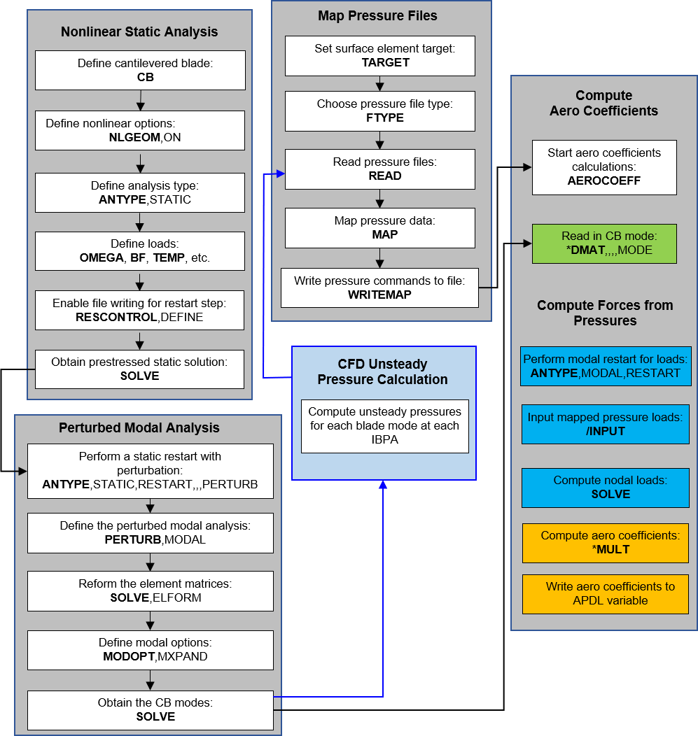
The steps for computing aero coefficients are as follows:
Create a blade alone model (no cyclic symmetry) or extract it from a full sector.
Perform a modal analysis.
Write mode shapes to a file.
Pass mode shapes to a CFD analysis tool.
Using mode shapes to prescribe displacements, obtain pressures from a flutter or aerodamping CFD analysis.
Write pressure file that is compatible with /MAP processor (see FTYPE).
Map pressure data from file using /MAP processor.
Compute aero coefficients (AEROCOEFF)
More information on these steps is provided in the following sections:
The AEROCOEFF command requires a prior cantilevered blade modal analysis without cyclic symmetry defined. All files needed for a modal analysis restart as described in Modal Analysis Restart must be obtained during the cantilevered blade modal analysis and must be present when the AEROCOEFF command is issued. Prior to issuing the AEROCOEFF command, the jobname must be changed to match the file names of the modal restart files.
Pressures from CFD flutter analyses must be available before issuing the AEROCOEFF command. These pressure profiles can be obtained using a CFX flutter analysis or from other CFD flutter analyses and mapped to the structural mesh according to Unidirectional Pressure Mapping: CFD to Mechanical APDL in the Coupled-Field Analysis Guide. The pressure files must be in the current working directory.
The aerodynamic coupling coefficients can be computed for all interblade phase angles for which mapped pressures are available and specified. For mistuned systems it is recommended that you compute aerodynamic coefficients for all interblade phase angles.
For each cantilevered blade mode used in a flutter analysis, the number of aerodynamic coupling coefficients should be equal to the number of sectors in the cyclic system. If there is more than one cantilevered blade mode producing pressures, then the number of aerodynamic coefficients per interblade phase angle will be greater than one. The number of aerodynamic coefficients per interblade phase angle goes with the number of cantilevered blade modes squared (for example, 1 mode = 12 coefficients, 2 modes = 22 = 4 coefficients).
The file formats that can be mapped are described in Modal Analysis Restart. An excerpt of a CFX flutter pressure file is shown below:
[Data]
Initial X    Initial Y   Initial Z    R1 Blade1.Passage  Real Pressure     Imaginary Pressure
[ m ]        [ m ]       [ m ]        Number [  ]        [ kg m^-1 s^-2 ]  [ kg m^-1 s^-2 ]
2.25E-04     9.57E-02    -6.25E-04    1.00E+00           -7.83E+02         -7.60E+02
2.21E-04     9.58E-02    -6.12E-04    1.00E+00           -8.88E+02         -8.69E+02
It is important to note that the CFX real pressure values labeled
Real Pressure are associated with the
negative imaginary part of the aero coefficient, and the
Imaginary Pressure is associated with
the real part of the aero coefficient. This convention must be followed if
using a non-CFX file format in conjunction with the
AEROCOEFF command.
Also note that the aero coupling coefficients in Mechanical APDL are associated with the left-hand side of the equation or the system, whereas the pressures provided by CFX are a right-hand side term. Therefore, these values are effectively negated in order to move them to the system as is the convention for recognizing aero coupling in Mechanical APDL. Again, this convention should be followed if using a non-CFX file format.
The CFX-generated pressure files may have a Traveling Wave
Flag value in the file header:
Nodal Diameter = -2 Mode Multiplier = 2.75505184E-004 Traveling Wave Flag = -1
The Traveling Wave Flag (TWF) operates on
the Nodal Diameter
(NDCFX). The actual nodal diameter equals the
Nodal Diameter multiplied by the
Traveling Wave Flag value. In the
header shown above, the actual nodal diameter is:

This computed nodal diameter number can then be converted to interblade
phase angle number, which can be specified in a numerical array that you
input for AeroSpecs on the
AEROCOEFF command.
It is important to ensure that the aerodynamic coefficients entered are scaled
to be compatible with the current mode-superposition harmonic cyclic symmetry
workflow. This workflow has cantilevered blade modes that have been
mass-normalized. However, it is common for structural mode shapes to be
normalized such that the maximum amplitude is equal to one and then further
scaled for use in a CFD flutter analysis. In this case, the relationship between
the CFD and structural modes is  . The aerodynamic coupling coefficients computed this way are
not directly compatible with the mode-superposition harmonic cyclic symmetry
workflow. The coefficients can be adjusted to be compatible with the structural
system by performing the inverse operations that were performed in the CFD
calculations and specifying that scaling value(s) in the
AEROCOEFF command using the
. The aerodynamic coupling coefficients computed this way are
not directly compatible with the mode-superposition harmonic cyclic symmetry
workflow. The coefficients can be adjusted to be compatible with the structural
system by performing the inverse operations that were performed in the CFD
calculations and specifying that scaling value(s) in the
AEROCOEFF command using the
AeroScalar option. In this scaling scenario, the
specified value would be  .
.
If the CFD pressure files are produced by CFX, information about the scaling is provided in the file header as shown below:
[Name]
Export Surface 1

[Parameters]
Ncompt = 1
Nnodes = 8002
Rotation Axis From = 0.00000000 [m]	 0.00000000 [m]	 0.00000000 [m]
Rotation Axis To   = 0.00000000 [m]	 0.00000000 [m]	 1.00000000 [m]
Rotating Speed     = 1679.99809 [s^-1 rad]
Frequency          = 534.649611 [Hz]
Nodal Diameter     = 5
Mode Multiplier    = 2.755051845E-04
...
The Mode Multiplier provides the value
that was used by CFX to multiply the original mass normalized structural
mode. To undo any normalizations and scaling done by CFX and rescale the
pressures for use in the structural forced response, the following
expression can be used for aero scaling:

This value can then be input in the AEROCOEFF command.
If the AutoFileRead option of the
AEROCOEFF command is used, the scaling values
(Mode Multiplier) from the CFD file
header are automatically used, and the AeroScalar
input is ignored.
/filname,test
/input,fe_mesh,dat			! Finite element mesh - Blade only

esel,s,type,,1				! Select blade elements
cm,BladeElem,elem			! form an element component
allse,all,all

fini
save
/com,-----------------------------------------------
/com, Pressure Mapping for Aero Coupling
/com,-----------------------------------------------
nBlade = 11				! specify number of blades
nmode = 1				! specify number of mode

*DIM,NodalDiamAero,array,nBlade
NodalDiamAero(1:11) = 0,1,2,3,4,5,6,7,8,9,10
*get,nAeNDs,PARM,NodalDiamAero,DIM,1

/com,-------------------------------------------------------
/com, CFX Data (Mode # 1)
/com, Exported CFX files in .CSV file format for all IBPA's
/com,-------------------------------------------------------
*DIM,AeroFileNames,string,38,nBlade

AeroFileNames(1,1) ='Blades_11_mode_1_ND_0.csv'	! file for Nodal Diameter = 0
AeroFileNames(1,2) ='Blades_11_mode_1_ND_pos_1.csv'	! file for Nodal Diameter = +1
AeroFileNames(1,3) ='Blades_11_mode_1_ND_pos_2.csv'	! file for Nodal Diameter = +2
AeroFileNames(1,4) ='Blades_11_mode_1_ND_pos_3.csv'	! file for Nodal Diameter = +3
AeroFileNames(1,5) ='Blades_11_mode_1_ND_pos_4.csv'	! file for Nodal Diameter = +4
AeroFileNames(1,6) ='Blades_11_mode_1_ND_pos_5.csv'	! file for Nodal Diameter = +5
AeroFileNames(1,7) ='Blades_11_mode_1_ND_neg_5.csv'	! file for Nodal Diameter = -5
AeroFileNames(1,8) ='Blades_11_mode_1_ND_neg_4.csv'	! file for Nodal Diameter = -4
AeroFileNames(1,9) ='Blades_11_mode_1_ND_neg_3.csv'	! file for Nodal Diameter = -3
AeroFileNames(1,10) ='Blades_11_mode_1_ND_neg_2.csv'	! file for Nodal Diameter = -2
AeroFileNames(1,11) ='Blades_11_mode_1_ND_neg_1.csv'	! file for Nodal Diameter = -1

parsav,all,tempMap,parm
parres,change,tempMap,parm

/com,-----------------------------------------------
/com, Mapping for all IBPA's
/com,-----------------------------------------------
*DO,ii,1,nAeNDs
	/map
	target,pressure_faces
	FTYPE, cfxtbr,1
	READ, AeroFileNames(1,ii)
	/show,png,rev
	plgeom
	map,,2,,1,
	plmap,target
    plmap,target,,,1
	plmap,source
    plmap,source,,,1
	plmap,both
    plmap,both,,,1
	/show,close
	WRITEMAP, 'mappedHI%NodalDiamAero(ii)%.dat'
	finish
*ENDDO

*get,_AeroCoeffJobNm,active,0,jobnam
parsav,all,AeroParm,parm
resume,BeforeMapping,db
parres,new,AeroParm,parm

/com,-----------------------------------------------
/com, Blade Alone Mode Shape (NON-CYCLIC)
/com,-----------------------------------------------
/prep7
cyclic,off   		!Cyclic symmetry is off
fini
/com,-----------------------------------------------
/com, Solution Controls for Static Solve
/com,-----------------------------------------------
/solu
antype,0              ! static analysis
neqit,1,force
pred,off
eqsl,pcg,1e-8,,,,,,1

cntr,print,1         ! print out contact info and also make no initial contact an error
nldiag,cont,iter     ! print out contact info each equilibrium iteration
resc,linear,last     ! Turn on restart files due to future eigen analysis intent

cgom,%_loadvari91x%,%_loadvari91y%,%_loadvari91z%	! CGOMEGA loading
nsub,1,1,1
time,1.

stabilize,off                   	! Stabilization turned OFF by user

cmsel,s,InterfaceNodes,node	! Select interface nodes between the blade and hub
d,all,all			! Apply constraints to all the nodes
allse,all,all
cmsel,s,BladeElem,elem		! Select blade elements
nsle
esel,a,type,,2			! also select blade surface elements
solve
fini
/com,-----------------------------------------------
/com, Solution Controls for Perturbed Modal Solve
/com,-----------------------------------------------
/solu
antype,,restart,,,perturbation
perturb,modal,,CURRENT,DZEROKEEP    	! pre-stress modal analysis
solve, elform

modopt,lanb,nmode,
mxpand,-1,,,no,,no   			! don't expand modes
cgomega,0,0,0

outres,erase
outres,all,none

solve
fini
/com,-----------------------------------------------
/com, File Names of Mapped Pressures From CFD
/com,-----------------------------------------------
*DIM,AeroMappedFileNames,string,32,nBlade

AeroMappedFileNames(1,1) ='mappedHI0.dat'
AeroMappedFileNames(1,2) ='mappedHI1.dat'
AeroMappedFileNames(1,3) ='mappedHI2.dat'
AeroMappedFileNames(1,4) ='mappedHI3.dat'
AeroMappedFileNames(1,5) ='mappedHI4.dat'
AeroMappedFileNames(1,6) ='mappedHI5.dat'
AeroMappedFileNames(1,7) ='mappedHI6.dat'
AeroMappedFileNames(1,8) ='mappedHI7.dat'
AeroMappedFileNames(1,9) ='mappedHI8.dat'
AeroMappedFileNames(1,10) ='mappedHI9.dat'
AeroMappedFileNames(1,11) ='mappedHI10.dat'

/com,-----------------------------------------------
/com, Aero Scaling Factor
/com,-----------------------------------------------
*dim,AeroScaling,array,nmode

ModeMultiplier = 2.755051845E-04
AeroScaling(1) = 1/ModeMultiplier    ! Aero Scaling factor

/com,-----------------------------------------------
/com, Aero Specification
/com,-----------------------------------------------
*dim,AeroSpecs,array,3,nBlade

AeroSpecs(1,1)=0,1,1
AeroSpecs(1,2)=1,1,1
AeroSpecs(1,3)=2,1,1
AeroSpecs(1,4)=3,1,1
AeroSpecs(1,5)=4,1,1
AeroSpecs(1,6)=5,1,1
AeroSpecs(1,7)=6,1,1
AeroSpecs(1,8)=7,1,1
AeroSpecs(1,9)=8,1,1
AeroSpecs(1,10)=9,1,1
AeroSpecs(1,11)=10,1,1

/solu
aerocoeff,blade,'AeroMappedFileNames','AeroSpecs',AeroScaling,nBlade
fini

/com, --------------------------------------------------------------------
/com, MECHANICAL APDL AERO DAMPING COEFFICENTS
/com, --------------------------------------------------------------------
*stat,testAeroArray
/filname,test
/input,fe_mesh,dat			! Finite element mesh - Blade only

esel,s,type,,1				! Select blade elements
cm,BladeElem,elem			! form an element component
allse,all,all

fini
save
/com,-----------------------------------------------
/com, Pressure Mapping for Aero Coupling
/com,-----------------------------------------------
nBlade = 11				! specify number of blades
nmode = 2				! specify number of modes
dim1 = nBlade*nmode

*DIM,AeroIndx,array,dim1
AeroIndx(1:11) = 0,1,2,3,4,5,6,7,8,9,10
AeroIndx(12:22) = 11,12,13,14,15,16,17,18,19,20,21
*get,nAeNDs,PARM,AeroIndx,DIM,1

/com,-------------------------------------------------------
/com, CFX Data (Mode # 1 and Mode # 2)
/com, Exported CFX files in .CSV file format for all IBPA's
/com,-------------------------------------------------------
*DIM,AeroFileNames,string,38,dim1

/com, Mode # 1 CFX Data
AeroFileNames(1,1) ='Blades_11_mode_1_ND_0.csv'	! Nodal Diameter = 0, Mode = 1
AeroFileNames(1,2) ='Blades_11_mode_1_ND_pos_1.csv'	! Nodal Diameter = +1, Mode = 1
AeroFileNames(1,3) ='Blades_11_mode_1_ND_pos_2.csv'	! Nodal Diameter = +2, Mode = 1
AeroFileNames(1,4) ='Blades_11_mode_1_ND_pos_3.csv'	! Nodal Diameter = +3, Mode = 1
AeroFileNames(1,5) ='Blades_11_mode_1_ND_pos_4.csv'	! Nodal Diameter = +4, Mode = 1
AeroFileNames(1,6) ='Blades_11_mode_1_ND_pos_5.csv'	! Nodal Diameter = +5, Mode = 1
AeroFileNames(1,7) ='Blades_11_mode_1_ND_neg_5.csv'	! Nodal Diameter = -5, Mode = 1
AeroFileNames(1,8) ='Blades_11_mode_1_ND_neg_4.csv'	! Nodal Diameter = -4, Mode = 1
AeroFileNames(1,9) ='Blades_11_mode_1_ND_neg_3.csv'	! Nodal Diameter = -3, Mode = 1
AeroFileNames(1,10) ='Blades_11_mode_1_ND_neg_2.csv'	! Nodal Diameter = -2, Mode = 1
AeroFileNames(1,11) ='Blades_11_mode_1_ND_neg_1.csv'	! Nodal Diameter = -1, Mode = 1

/com, Mode # 2 CFX Data
AeroFileNames(1,12) ='Blades_11_mode_2_ND_0.csv'	! Nodal Diameter = 0, Mode = 2
AeroFileNames(1,13) ='Blades_11_mode_2_ND_pos_1.csv'	! Nodal Diameter = +1, Mode = 2
AeroFileNames(1,14) ='Blades_11_mode_2_ND_pos_2.csv'	! Nodal Diameter = +2, Mode = 2
AeroFileNames(1,15) ='Blades_11_mode_2_ND_pos_3.csv'	! Nodal Diameter = +3, Mode = 2
AeroFileNames(1,16) ='Blades_11_mode_2_ND_pos_4.csv'	! Nodal Diameter = +4, Mode = 2
AeroFileNames(1,17) ='Blades_11_mode_2_ND_pos_5.csv'	! Nodal Diameter = +5, Mode = 2
AeroFileNames(1,18) ='Blades_11_mode_2_ND_neg_5.csv'	! Nodal Diameter = -5, Mode = 2
AeroFileNames(1,19) ='Blades_11_mode_2_ND_neg_4.csv'	! Nodal Diameter = -4, Mode = 2
AeroFileNames(1,20) ='Blades_11_mode_2_ND_neg_3.csv'	! Nodal Diameter = -3, Mode = 2
AeroFileNames(1,21) ='Blades_11_mode_2_ND_neg_2.csv'	! Nodal Diameter = -2, Mode = 2
AeroFileNames(1,22) ='Blades_11_mode_2_ND_neg_1.csv'	! Nodal Diameter = -1, Mode = 2

parsav,all,tempMap,parm
parres,change,tempMap,parm
/com,-----------------------------------------------
/com, Mapping for all IBPA's
/com,-----------------------------------------------
*DO,ii,1,nAeNDs
	/map
	target,pressure_faces
	FTYPE, cfxtbr,1
	READ, AeroFileNames(1,ii)
	/show,png,rev
	plgeom
	map,,2,,1,
	plmap,target
	plmap,target,,,1
	plmap,source
	plmap,source,,,1
	plmap,both
    	plmap,both,,,1
	/show,close
	WRITEMAP,'mapped%AeroIndx(ii)%.dat'
	finish
*ENDDO

*get,_AeroCoeffJobNm,active,0,jobnam
parsav,all,AeroParm,parm
resume,BeforeMapping,db
parres,new,AeroParm,parm

/com,-----------------------------------------------
/com, Blade Alone Mode Shape (NON-CYCLIC)
/com,-----------------------------------------------
/prep7
cyclic,off   			!Cyclic symmetry is off
fini
/com,-----------------------------------------------
/com, Solution Controls for Static Solve
/com,-----------------------------------------------
/solu
antype,0                   	! static analysis
neqit,1,force
pred,off
eqsl,pcg,1e-8,,,,,,1

cntr,print,1         ! print out contact info and also make no initial contact an error
nldiag,cont,iter     ! print out contact info each equilibrium iteration
resc,linear,last     ! Turn on restart files due to future eigen analysis intent

cgom,%_loadvari91x%,%_loadvari91y%,%_loadvari91z%	! CGOMEGA loading
nsub,1,1,1
time,1.

stabilize,off                   	! Stabilization turned OFF by user

cmsel,s,InterfaceNodes,node	! Select interface nodes between the blade and hub
d,all,all			! Apply constraints to all the nodes
allse,all,all
cmsel,s,BladeElem,elem		! Select blade elements
nsle
esel,a,type,,2			! also select blade surface elements
solve
fini
/com,-----------------------------------------------
/com, Solution Controls for Perturbed Modal Solve
/com,-----------------------------------------------
/solu
antype,,restart,,,perturbation
perturb,modal,,CURRENT,DZEROKEEP    	! pre-stress modal analysis
solve, elform

modopt,lanb,nmode,
mxpand,-1,,,no,,no   			! don't expand modes
cgomega,0,0,0

outres,erase
outres,all,none

solve
fini
/com,-----------------------------------------------
/com, File Names of Mapped Pressures From CFD
/com,-----------------------------------------------
nspec = 4
dim2 = nBlade*nspec
*DIM,AeroMappedFileNames,string,32,dim2

AeroMappedFileNames(1,1) ='mapped0.dat'
AeroMappedFileNames(1,2) ='mapped1.dat'
AeroMappedFileNames(1,3) ='mapped2.dat'
AeroMappedFileNames(1,4) ='mapped3.dat'
AeroMappedFileNames(1,5) ='mapped4.dat'
AeroMappedFileNames(1,6) ='mapped5.dat'
AeroMappedFileNames(1,7) ='mapped6.dat'
AeroMappedFileNames(1,8) ='mapped7.dat'
AeroMappedFileNames(1,9) ='mapped8.dat'
AeroMappedFileNames(1,10) ='mapped9.dat'
AeroMappedFileNames(1,11) ='mapped10.dat'

AeroMappedFileNames(1,12) ='mapped11.dat'
AeroMappedFileNames(1,13) ='mapped12.dat'
AeroMappedFileNames(1,14) ='mapped13.dat'
AeroMappedFileNames(1,15) ='mapped14.dat'
AeroMappedFileNames(1,16) ='mapped15.dat'
AeroMappedFileNames(1,17) ='mapped16.dat'
AeroMappedFileNames(1,18) ='mapped17.dat'
AeroMappedFileNames(1,19) ='mapped18.dat'
AeroMappedFileNames(1,20) ='mapped19.dat'
AeroMappedFileNames(1,21) ='mapped20.dat'
AeroMappedFileNames(1,22) ='mapped21.dat'

AeroMappedFileNames(1,23) ='mapped0.dat'
AeroMappedFileNames(1,24) ='mapped1.dat'
AeroMappedFileNames(1,25) ='mapped2.dat'
AeroMappedFileNames(1,26) ='mapped3.dat'
AeroMappedFileNames(1,27) ='mapped4.dat'
AeroMappedFileNames(1,28) ='mapped5.dat'
AeroMappedFileNames(1,29) ='mapped6.dat'
AeroMappedFileNames(1,30) ='mapped7.dat'
AeroMappedFileNames(1,31) ='mapped8.dat'
AeroMappedFileNames(1,32) ='mapped9.dat'
AeroMappedFileNames(1,33) ='mapped10.dat'

AeroMappedFileNames(1,34) ='mapped11.dat'
AeroMappedFileNames(1,35) ='mapped12.dat'
AeroMappedFileNames(1,36) ='mapped13.dat'
AeroMappedFileNames(1,37) ='mapped14.dat'
AeroMappedFileNames(1,38) ='mapped15.dat'
AeroMappedFileNames(1,39) ='mapped16.dat'
AeroMappedFileNames(1,40) ='mapped17.dat'
AeroMappedFileNames(1,41) ='mapped18.dat'
AeroMappedFileNames(1,42) ='mapped19.dat'
AeroMappedFileNames(1,43) ='mapped20.dat'
AeroMappedFileNames(1,44) ='mapped21.dat'

/com,-----------------------------------------------
/com, Aero Scaling Factor
/com,-----------------------------------------------
*dim,AeroScaling,array,nmode
ModeMultiplier = 2.755051845E-04
AeroScaling(1) = 1/ModeMultiplier    ! Aero Scaling factor

ModeMultiplier = 4.035663213E-04
AeroScaling(2) = 1/ModeMultiplier    ! Aero Scaling factor

/com,-----------------------------------------------
/com, Aero Specification
/com,-----------------------------------------------
*dim,AeroSpecs,array,3,dim2

AeroSpecs(1,1)=0,1,1
AeroSpecs(1,2)=1,1,1
AeroSpecs(1,3)=2,1,1
AeroSpecs(1,4)=3,1,1
AeroSpecs(1,5)=4,1,1
AeroSpecs(1,6)=5,1,1
AeroSpecs(1,7)=6,1,1
AeroSpecs(1,8)=7,1,1
AeroSpecs(1,9)=8,1,1
AeroSpecs(1,10)=9,1,1
AeroSpecs(1,11)=10,1,1

AeroSpecs(1,12)=0,1,2
AeroSpecs(1,13)=1,1,2
AeroSpecs(1,14)=2,1,2
AeroSpecs(1,15)=3,1,2
AeroSpecs(1,16)=4,1,2
AeroSpecs(1,17)=5,1,2
AeroSpecs(1,18)=6,1,2
AeroSpecs(1,19)=7,1,2
AeroSpecs(1,20)=8,1,2
AeroSpecs(1,21)=9,1,2
AeroSpecs(1,22)=10,1,2

AeroSpecs(1,23)=0,2,1
AeroSpecs(1,24)=1,2,1
AeroSpecs(1,25)=2,2,1
AeroSpecs(1,26)=3,2,1
AeroSpecs(1,27)=4,2,1
AeroSpecs(1,28)=5,2,1
AeroSpecs(1,29)=6,2,1
AeroSpecs(1,30)=7,2,1
AeroSpecs(1,31)=8,2,1
AeroSpecs(1,32)=9,2,1
AeroSpecs(1,33)=10,2,1

AeroSpecs(1,34)=0,2,2
AeroSpecs(1,35)=1,2,2
AeroSpecs(1,36)=2,2,2
AeroSpecs(1,37)=3,2,2
AeroSpecs(1,38)=4,2,2
AeroSpecs(1,39)=5,2,2
AeroSpecs(1,40)=6,2,2
AeroSpecs(1,41)=7,2,2
AeroSpecs(1,42)=8,2,2
AeroSpecs(1,43)=9,2,2
AeroSpecs(1,44)=10,2,2

/solu
aerocoeff,blade,'AeroMappedFileNames','AeroSpecs',AeroScaling,nBlade
fini

/com, --------------------------------------------------------------------
/com, MECHANICAL APDL AERO DAMPING COEFFICENTS
/com, --------------------------------------------------------------------

*stat,testAeroArray