


The steps to use an iterative distortion compensation analysis are summarized in the table below. Details are described in the following sections:
| Iterative Compensation Workflow at a Glance | |
|---|---|
| Simulation Step | Considerations for Iterative Compensation |
| 1. Set up AM simulation | Set up an AM simulation such as LPBF
thermal-structural, LPBF inherent
strain, or sintering. Perform the typical steps in the simulation
until just before the solve step. Use unshared topology between part bodies and/or predefined supports. Use a Cartesian, voxelized, or layered tetrahedrons mesh method. Each generated support must be inserted under its own unique Support Group. For an explanation of support types, see Identify and/or Generate Supports. Use only location-based scoping for boundary conditions. (See Known Issues and Limitations). Consider suppressing the calculation of stresses and strains if you are only interested in distortion (Static Structural → Analysis Settings → Output Controls) |
| 2. Load add-on | Load the Distortion Compensation Add-on |
| 3. Set distortion compensation settings | Specify whether the target geometry will be generated and refaceted by Mechanical (Use Reference Geometry = No, default) or read in as a user defined file (Use Reference Geometry = Yes). Identify geometries to be compensated, including any predefined supports. STL Supports are included in compensation automatically and do not need to be selected. Set convergence criteria. Average Deviation and Maximum Deviation reflect part tolerances. Maximum Iterations sets limit on number of iterative solutions. Note the state of Remesh Geometry as Yes or No, set automatically depending on the simulation system (Yes for LPBF simulations, No for sintering simulations). For LPBF simulations, set refaceting settings, which allow you to control the refaceted mesh size for better stl quality (Curvature Min Size, Max Size, Growth Rate, Curvature Normal Angle). Set advanced options, including Distortion Compensation Factor. By default, Zero Deformations at Base = Yes for LPBF simulations, our recommended setting when cutoff is simulated. You can change the zero-deformation transition length using Zero Deformation Gap. Set output controls. Set Save Iteration Results = Yes if you want to save compensated geometries from all iterations. Set restart controls. If you anticipate using restarts, set Generate Restart Points = Yes before starting the initial compensation analysis. |
| 4. Show and save refaceted geometry |
|
| 5. Solve the analysis | Requires an Additive Suite license |
| 6. Visualize convergence | Review convergence history during and after the solution
(Distortion Compensation → Convergence History)
For a successful analysis, look for the informational message "Converged within tolerances." |
| 7. Evaluate results | Statistics are available for the most recently completed iteration in the Details view of the Distortion Compensation object. Items include Iterations Completed, Average Deviation, and Maximum Deviation. |
| 8. Export STL | |
| Optional: Restart a Compensation | As needed, use Restart Point to select the iteration from which the compensation will go back and restart. |
| Optional: Restore Original Model | |

You can see the effect of your refaceting settings immediately. From the Distortion Compensation Add-on ribbon, click Show Refaceted Geometry of Parts or Show Refaceted Geometry of Supports to generate and display the faceted geometry. In the graphics window, a second window appears to the left, allowing you to compare the faceted geometry to whatever is showing in the graphics window, such as the layered mesh, for instance. It may take a couple of minutes to generate the refaceted mesh for large models.

Exporting the Reference Geometry
The refaceted reference geometries can be saved by clicking the Export Reference Geometry button on the Distortion Compensation Add-on ribbon, or right-clicking the Distortion Compensation object and selecting Export Reference Geometry.
By default (Save Iteration Results = No), the simulation will save the compensated geometries as stl files for the last iteration only.
Setting Save Iteration Results to Yes saves the compensated geometries from every iteration in the project directory in a subfolder called Iteration Results. This folder, along with its contents, will be reset if a simulation is restarted. File names include the iteration number. Support bodies are identified by body ID.
In the following example, the part is named compensated_stl0, there are no supports, and there are 3 compensation iterations.
compensated_stl0_Iteration_1.stl
compensated_stl0_Iteration_2.stl
compensated_stl0_Iteration_3.stl
In the next example, again with 3 compensation iterations, the part is compensated_stl0 and there are two STL Support bodies with IDs of 22 and 45.
compensated_stl0_Iteration_1.stl
compensated_stl22_Iteration_1.stl
compensated_stl45_Iteration_1.stl
compensated_stl0_Iteration_2.stl
compensated_stl22_Iteration_2.stl
compensated_stl45_Iteration_2.stl
compensated_stl0_Iteration_3.stl
compensated_stl22_Iteration_3.stl
compensated_stl45_Iteration_3.stl
All compensated stl files are exported in millimeter units for consistency between part and supports, regardless of the unit system of the original part.
Exporting the Final, Compensated Geometry
The final, compensated geometries can be saved by clicking the Export STL button on the Distortion Compensation Add-on ribbon, or right-clicking the Distortion Compensation object and selecting Export STL File. Assuming a converged solution, this should be the geometry used for printing.
The compensated geometries are written to a folder. For models containing supports, separate files are exported for the part and the supports. They will be named as follows:
compensated_stl0_Iteration_x.stl
with x corresponding to the final iteration. All compensated stl files are exported in millimeter units for consistency between part and supports, regardless of the unit system of the original part.
During the iterative compensation solution, you can view the convergence of distortion toward the tolerance criteria by viewing the convergence history chart.
Under the Iterative Compensation object, click the Convergence History child object. A plot of overall convergence history is shown. The red line indicates average deviation compared to the Average Deviation criteria (dotted line) and the blue line indicates maximum deviation compared to the Maximum Deviation criteria (dotted line).

If the iterative compensation converges within tolerances on the first iteration, no compensated geometry is generated, and the starting geometry should be sufficient to use for printing.
A restart capability for iterative distortion compensation enables you to modify parameters like the compensation factor or the average/maximum deviation once an analysis has begun. If you anticipate using restarts, you must set Generate Restart Points to Yes before starting the initial compensation analysis.
Any time after at least one distortion compensation iteration is completed, you can use the Restart Controls feature. This allows you to pick a specific iteration from which to resume the distortion compensation process. Note that selecting iteration 1 will essentially restart distortion compensation from the beginning (the same as restoring the original model).
To initiate a restart, follow these steps:
On the Iterative Compensation object, under Restart Controls, use the drop-down menu labeled Restart Point to select your desired restart point. As an example, choosing Iteration 2 will rerun the second iteration using the results of the first iteration as the starting point.
Upon selecting a restart point, a warning message will appear, asking you to confirm your choice:
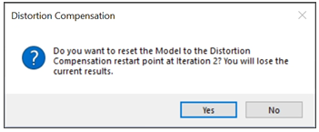
Choose Yes, upon which the application will configure the necessary geometry and settings internally for the restart.
Right-click the Solution object within the tree and select Solve. This will activate the solve procedure, and the distortion compensation will proceed, running the specified number of steps based on the maximum iteration value from the selected restart point.
After compensation has completed, you can use Restore Original Model to reset the model tree back to the state before a distortion compensation solution. Build geometries (part and supports) will be reset to the original geometries, and scoping, named selections, contact, and other items will be reset to their states before iterative compensation began. This action makes it easier to completely re-run an iterative compensation with new settings.
Limitation: Restore Original Model works when you have opened a saved Workbench project but does not work for an archived project file.
Limitation: Restore Original Model does not restore Generated Supports. You will need to manually reset Generated Supports.
With the Remesh Geometry = No on the Iterative Compensation object, Direct Morph is used to move existing nodes to compensate for deformations on previous iterations. Because of this, the mesh is not recreated and retains geometry and mesh scoping through each iteration. This Direct Morph option is recommended for sintering simulations.
Two additional options are available to benefit distortion compensation with sintering:
Translate Parts to Baseplate: If set to Yes, the sintered part is translated back onto the baseplate if the compensation caused the part to separate from, or penetrate, the plate.
Limitation: Large deformations may result in the part not being translated to the base correctly. Review your model carefully.
Turn on Contact Stabilization: If set to Yes, this option helps with convergence and ensures good contact between the part and the plate after the mesh is compensated.
For sintering simulations, the Zero Deformations at Base option is set to No by default, which differs from LPBF simulations where deformations at the build/base interface may not be as important.