The base to compute the equivalent beam properties is a generic straight box-like composite structure with constant cross section and constant composite layup along the length. A consequent equivalent beam model is built, and its frequencies are compared against the 3D model frequencies (SOLID185 elements).
 The fully
configured Workbench project is contained in a compressed file and can be downloaded
here. This configured project requires Release 2024 R2 or more recent
versions.
The fully
configured Workbench project is contained in a compressed file and can be downloaded
here. This configured project requires Release 2024 R2 or more recent
versions.
The section is shown in the following figure with the coarse mesh used to access the methodology. The material properties are listed in the table.
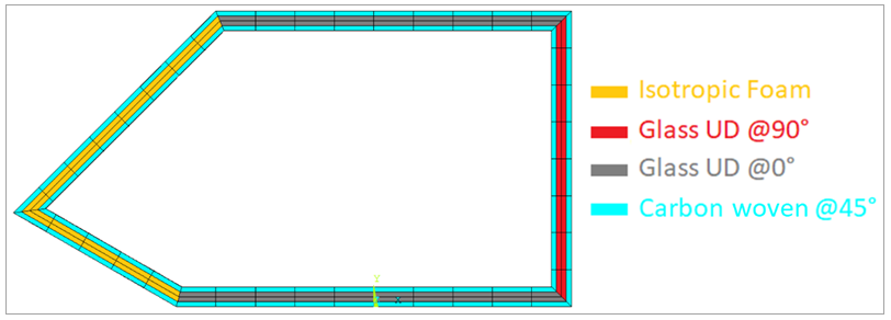
Table 4.1: Material Properties
| Foam | Glass UD | Carbon Woven | |
| Ex [Mpa] | 70 | 45000 | 61340 |
| Ey [Mpa] | 70 | 10000 | 61340 |
| Ez [Mpa] | 70 | 10000 | 6900 |
| Gxy [Mpa] | 26.92 | 5000 | 3300 |
| Gxz [Mpa] | 26.92 | 5000 | 2700 |
| Gyz [Mpa] | 26.92 | 3846.15 | 2700 |
| νxy | 0.3 | 0.3 | 0.04 |
| νxz | 0.3 | 0.3 | 0.3 |
| νyz | 0.3 | 0.4 | 0.3 |
| Density [t/mm3] | 6E-11 | 2.0E-09 | 1.42E-09 |
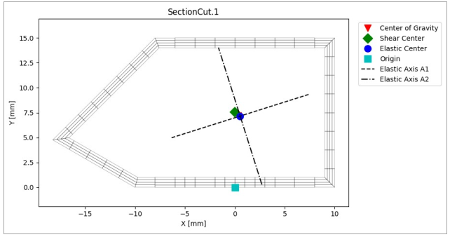
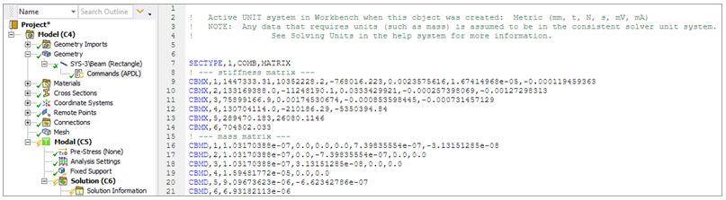
For this example, the reference point considered for the cross section properties is the Origin. The following shows the calculation result.
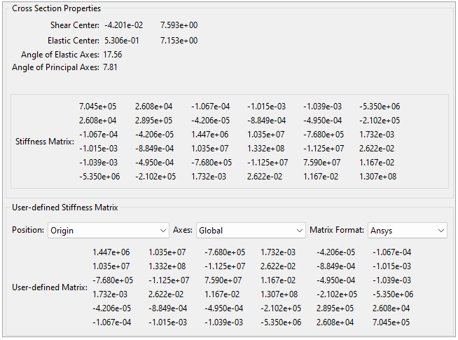
A simple straight beam of the desired length is created in SpaceClaim and meshed in the Mechanical application. The equivalent beam model is built in the Mechanical system Modal: Beam model (C) by adding an APDL snippet under the Geometry object in the Tree View. The results from the Section Cut computation in ACP are directly pasted here as shown below. Alternatively, a Python script could be inserted in ACP which automatically generates the APDL inputs (APDL file). This file can then be loaded by the Command Snippet object in the Mechanical. The Python script option enables further automation of the workflow.
Note: SpaceClaim is no longer included in the unified installer. Ansys recommends using Discovery Modeling to create geometries, or its alternative DesignModeler.
The beam is fixed on one end and the first six frequencies are calculated. The table below compares the results of the 3D solid model and equivalent beam model.
Table 4.2: Comparison of the 3D Solid Model and Equivalent Beam Model Results
| Frequency | 3D Model | Equivalent Beam | Diff. % |
| 1 | 82.574 | 82.152 | -0.511 |
| 2 | 95.958 | 95.484 | -0.494 |
| 3 | 509.19 | 504.95 | -0.833 |
| 4 | 592.73 | 589.07 | -0.617 |
| 5 | 1384.1 | 1372.7 | -0.824 |
| 6 | 1619.6 | 1610.5 | -0.562 |
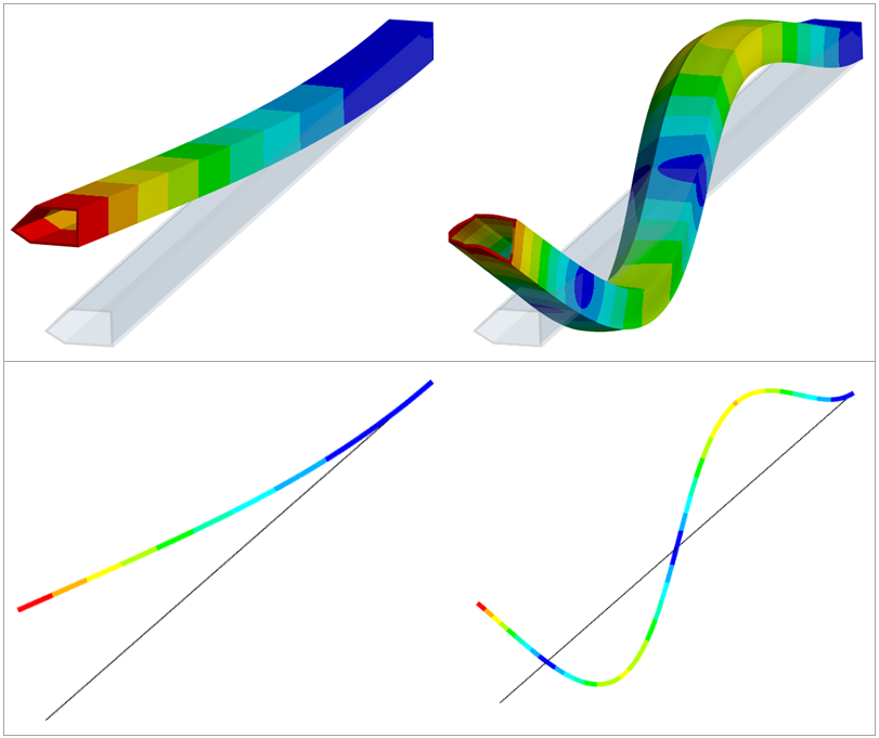
The following figure shows a comparison of the mode shapes for the first and fifth frequencies.
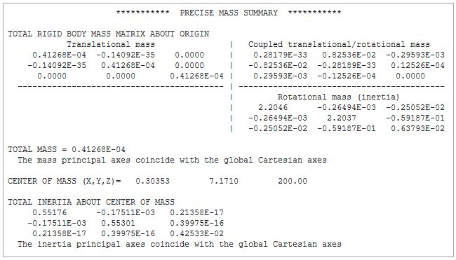
You may compare the data of the inertia properties for the 3D solid model and equivalent beam model using the reports below.
3D Solid Model
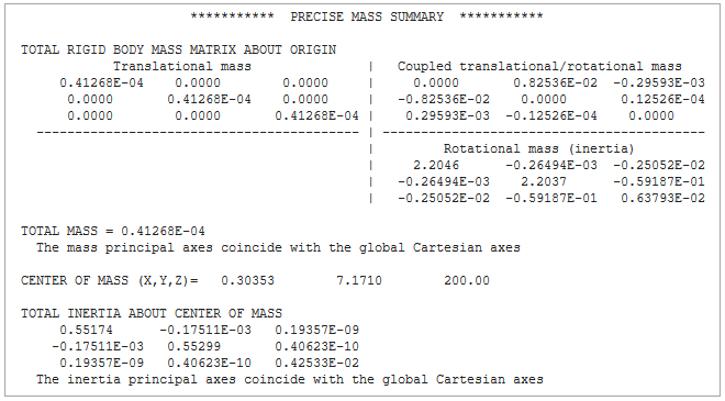
Equivalent Beam Model