To import into Mechanical the weld line locations from injection molding simulations, follow these steps:
Open Workbench and load the archive laptop_weldlines_2022R1_start.wbpz included in the tutorial download package.
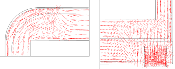
Double-click the Model cell B4 to open Ansys Mechanical. In the Mechanical Outline, select Element Orientation and adjust the Imported Fields options in the ribbon bar to review the principal fiber directions.
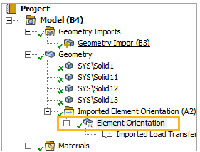
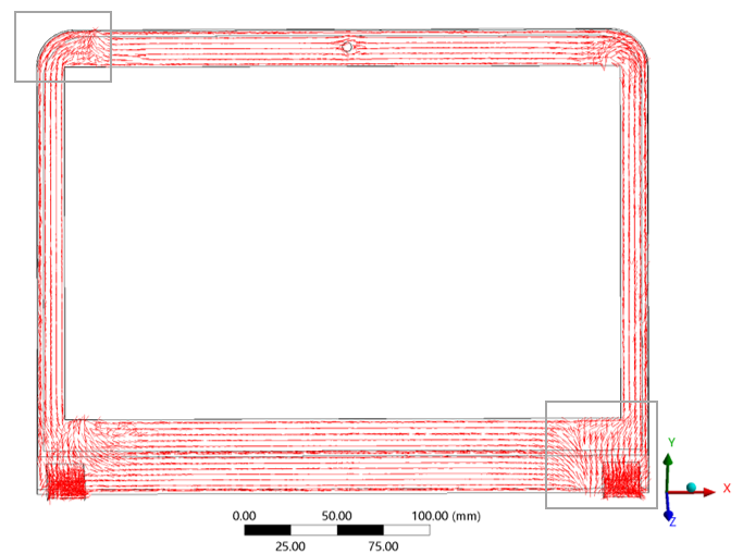
The change in orientation of the first principal fiber direction in the top-left and bottom-right corners of the frame already reveals the presence of weld lines. In the next step, we will import the exact weld line locations and angles predicted by a third-party injection molding simulation software.
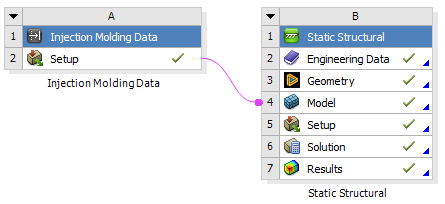
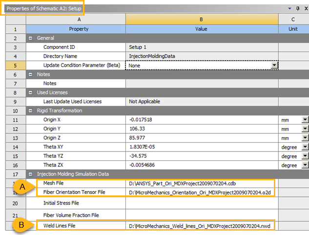
In the Workbench schematic, double-click the Setup cell A2 to open the properties of the Injection Molding Data system. The Mesh File and the Fiber Orientation Tensor File are already loaded (see A, below). For the Weld Lines File (B), select the following .nwd file that was included in the project download (you can find the link for downloading the project files here):
MicroMechanics_Weld_lines_Ori_MDXProject2009070204.nwd Right-click the Setup cell of Injection Molding Data system and click Update to import the corresponding files.
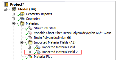
Double-click Model cell B4 to open Mechanical (when prompted, confirm to re-read the upstream data). In the Mechanical Outline, add a new Imported Material field:
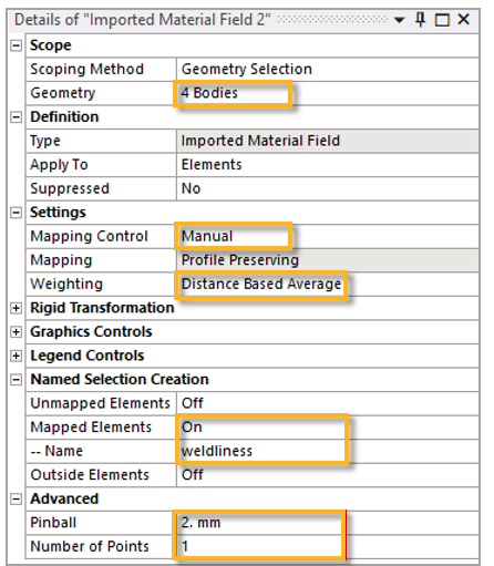
In the Details view, assign the body by selecting the geometry.
Choose a Manual Control in Mapping Control and select a Distance Based Average for Weighting.
Adjust Pinball and Number of Points as shown below to control the extent of the mapped weld line region.
Choose On for Mapped Elements in the Named Selection Creation section and specify
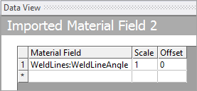
weldlinesas the Name. (This will add a Named Selection containing the elements where the weld lines angle is mapped.)In the Data View, assign the WeldLineAngle field
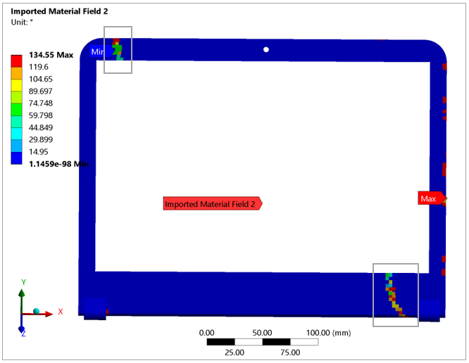
Right-click the second Imported Material Field in the Mechanical Outline and select Import Material Field.
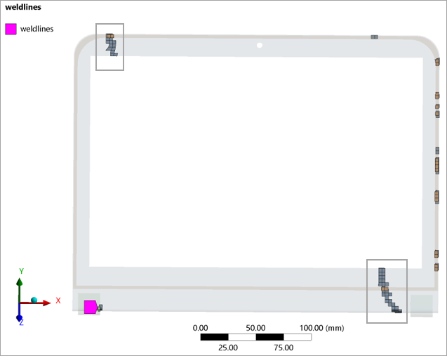
Select Imported Material Field 2 in the Mechanical Outline: an element-wise plot of the weld line angle is shown in the main view. Two major weld lines are now immediately recognizable from the contour plot.
In the Named Selections tab of the Mechanical Outline, select weldlines under Named Selection to visualize the elements of the model belonging to a weld line. Beside the two major weld lines, other smaller spots are present where flow fronts meet during the injection simulation.