


The following sections describe analysis using Classical Laminate Theory.
The laminate stiffness matrix is an 8 x 8 matrix that contains the ABD matrix (6 x 6) as well as the shear matrix C (2 x 2).
 | (5–1) |
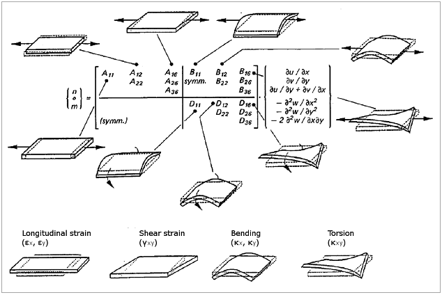
The ABD matrix of the laminate is the stiffness matrix of the laminate. A is the in-plane stiffness matrix, B describes the coupling between in-plane forces and bending moments and D is the flexural stiffness matrix. The B matrix becomes 0 in the case of a symmetrically balanced laminate.
In addition to the ABD terms the shear matrix C is evaluated as well. The shear matrix has form

 and
and  represent the
  and
and  stiffness, respectively.
The compliance matrix is an 8 x 8 matrix that contains the inverse of the ABD matrix and the inverse of the C matrix. The inverse of the ABD is also called the abd matrix (ABD -1).
The stiffness and compliance matrices can also be written in
a normalized form where  is the laminate thickness. The
normalized stiffness matrices ABD
* are:
is the laminate thickness. The
normalized stiffness matrices ABD
* are:
In-plane stiffness matrix:

Coupling matrix:

Flexural stiffness matrix:

Out-of-plane shear matrix:

And the normalized compliance matrices abd * are:
In-plane compliance matrix:

Coupling matrix:

Flexural compliance matrix:

Out-of-plane shear matrix:

The laminate engineering constants are derived from the normalized compliance matrices which can be compared with the ply compliance matrix. Therefore the in-plane engineering constants are derived from the normalized in-plane compliance matrix:
Laminate stiffness:

Laminate stiffness:

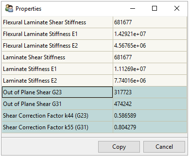
Laminate shear stiffness:

and the out-of-plane shear terms are derived from the normalized shear compliance matrix:
Shear correction factors:
 and k55
Out-of-plane shear stiffness:

Out-of-plane shear stiffness:

And the flexural constants are derived from the normalized flexural compliance matrix:
Flexural laminate stiffness:

Flexural laminate stiffness:

Flexural laminate shear stiffness:

In the case of coupling between in-plane and bending forces
( matrix has non-zero elements),
the engineering constants represents the case where the laminate is
free to curve when loaded with in-plane forces.
matrix has non-zero elements),
the engineering constants represents the case where the laminate is
free to curve when loaded with in-plane forces.
The out-of-plane shear stiffness matrix C is computed by:

where ti is the i-th ply thickness and G the i-th ply out-of-plane shear matrix (2x2) in the laminate coordinate system.
The laminate out-of-plane shear stiffnesses G31 and G23 are overestimated by the first order shear deformation theory. This can be overcome by using shear correction factors. ACP uses the theory developed by Isaksson [11] to compute the out-of-plane shear correction factors k44 and k55.
The final out-of-plane shear moduli are computed as:


where t is the total laminate thickness. So the shear correction factors are already included in laminate properties computed by ACP.
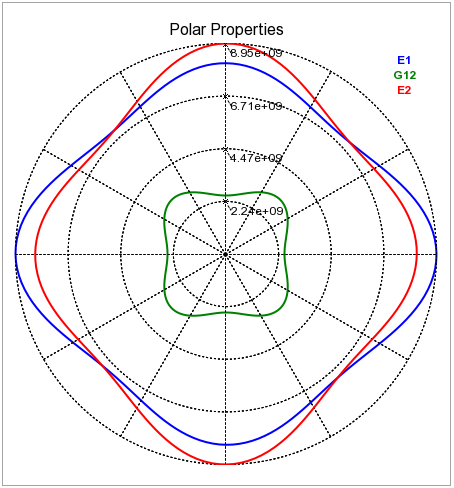
The polar plot shows the in-plane laminate engineering constants
of the laminate ( ,
, and
and  ) rotated by 0 to 360 degrees.
This plot highlights the anisotropy of the laminate and the influence
of the orientation.
) rotated by 0 to 360 degrees.
This plot highlights the anisotropy of the laminate and the influence
of the orientation.
The options Offset is Middle and Consider Coupling Effect allow you to modify the evaluation of the laminate properties.
Offset is Middle: This option moves the reference plane of the laminate to the middle (default: True). This option is useful since the layers in a FE analysis mostly have one offset direction and hence the reference plane is at the top or bottom of the laminate. This option reduces the coupling effect between in-plane and bending forces. It considers the results of the stiffness and compliance matrices, polar properties, and laminate engineering constants.
Consider Coupling Effect: The polar properties and laminate engineering constants are derived from the laminate compliance matrix (inverse ABD matrix) where, by default, the coupling effect is considered (default: True). This option allows you to neglect this effect which causes the polar properties and laminate engineering constants to represent the values of a symmetrically balanced laminate. Note that the coupling effect can significantly reduce the polar properties and laminate engineering constants.