


Radar Range Doppler Map Output Data
This topic describes the structure of a range-doppler map output.
The range doppler map corresponds to one type of possible processing of the radar raw response. It is a result of the processing of one dimension of the signal.
Note: Only the content of *.txt files is described in this guide. For
more details about the range doppler map output in protobuf format, refer to the
RangeDopplerResponseData page of the API documentation.
The radar sensor processes the input wave and is then able to provide a .txt file corresponding to the data of a complex range-Doppler map that gives the relative position and speed of the target object.
One complex range-Doppler map (meaning one .txt file) is generated per mode for each simulation time step.
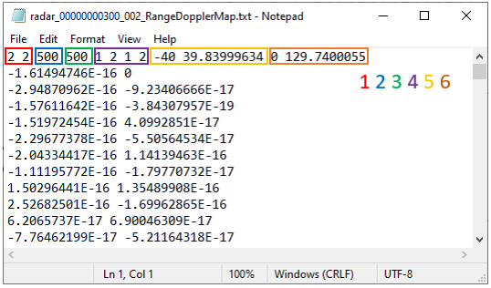
The output structure of the .txt result file is the following:
- Header:
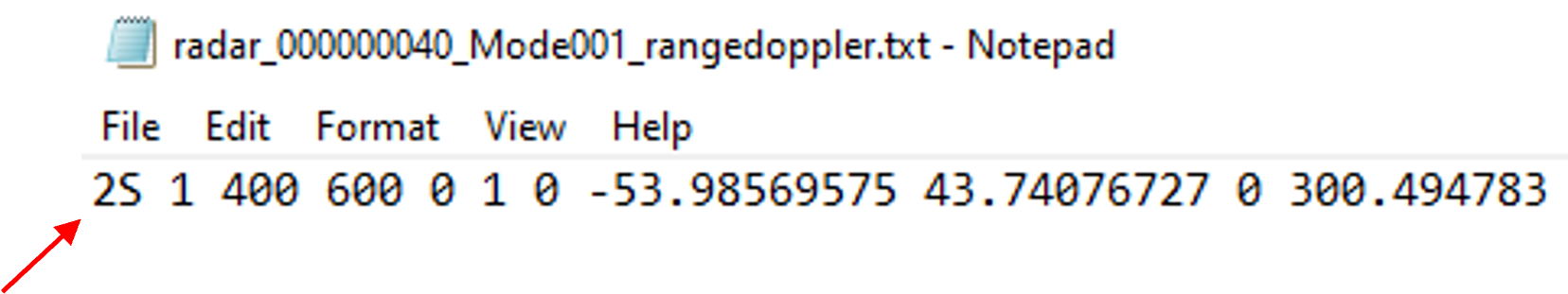
- Number of Tx and Rx AntennasNote: If the mode for which the .txt file is generated is simultaneous [Beta Feature], the number of Tx antennas is followed by the letter "S".
- Number of pixels of the Doppler scale (abscissa axis)
- Number of pixels of the Range scale (ordinate axis)
- IDs of the antennas played in the output: list of the Tx IDs, then list of the Rx IDs
- Min and Max of Doppler scale (in m/s)
- Min and Max of Range scale (in m)
- Number of Tx and Rx Antennas
- Following lines: Complex Value [real part] [imaginary part]
In this example, each frame has 2*2 channels and 500*500 data are produced for each channel:
- 1st channel for Tx1 and Rx1
- Abscissa1 Ordinate1
- ...
- Abscissa1 Ordinate500
- Abcissa2 Ordinate1
- ...
- Abcissa2 Ordinate500
- ...
- Abcissa500 Ordinate500
- 2nd channel for Tx1 and Rx2
- Abscissa1 Ordinate1
- ...
- Abscissa500 Ordinate500
- 3rd channel for Tx2 and Rx1
- Abscissa1 Ordinate1
- ...
- Abscissa500 Ordinate500
- 4th channel for Tx2 and Rx2
- Abscissa1 Ordinate1
- ...
- Abscissa500 Ordinate500