


Measure Grid Overview
The Measure Grid Overview describes how the horizontal and vertical Grids work with the Aiming Wall to assess the headlamp projection.
There are two Measure Grids and they may be displayed with the Aiming Wall:
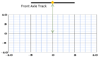
The Vertical Grid is linked to the Aiming Wall and allows you to verify the height of the projectors.
The Vertical Grid origin is centered on the projection of the Lighting System referential (whose origin is the center of the Front Axle track) on the Aiming Wall.
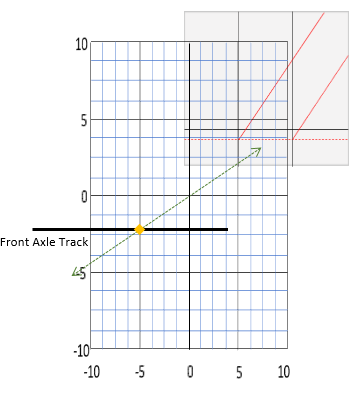
The Horizontal Grid allows you to verify how far away the projectors are.
Tip: When displaying the Horizontal Grid, you can display the Bird's View and then combine the measurement tool with the Value Picker.The Horizontal Grid is centered on the projection of the Lighting system Element on the Aiming Wall,
Each Measure Grid has a Main Grid and a Sub Grid.
The Main Grid parameters are presented in the table:
Parameter |
Description |
|---|---|
Size |
Sets the width (W) and height (H) in meter of the Main Grid. |
Step |
Sets the horizontal and vertical step in meter. |
Color |
Allows you to choose the color of the grid. |
The Sub Grid parameters are presented in the table:
Parameter |
Description |
|---|---|
Visibility |
Shows or hides the Sub Grid. |
Subdivisions |
Sets the number of subdivisions used to verify that the Step used is correct. |
Color |
allows you to choose the color of the grid. |
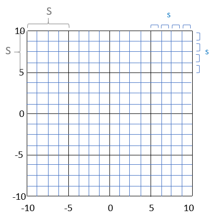
In this case, the Step (S) of the black Main Grid is 4 meters and the Subdivisions of the blue Sub Grid (s) is 4.