


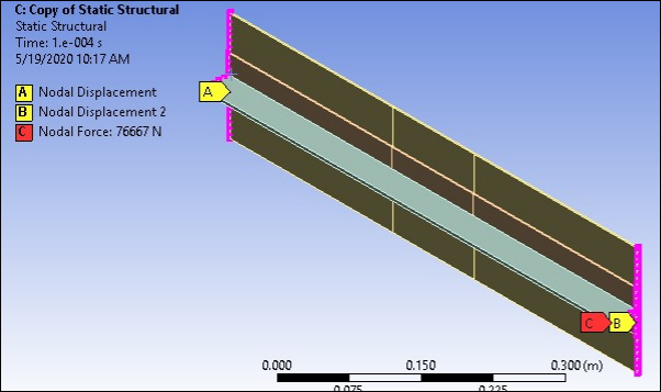
One end of the panel is completely constrained, as shown in the figure below. The other end is assumed rigid and allowed only uniform displacement in the longitudinal (global X) direction. To simulate these conditions, a pilot node is created and the CP command is used to couple the X displacement of the pilot node and the X displacement of all other nodes at this end.
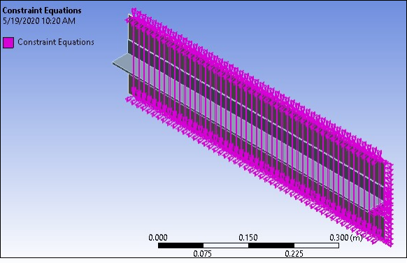
The periodic symmetry requires that any node on one cut boundary of the representative model moves in the same way as the corresponding node at the other cut boundary. The coupling condition (CP) is shown in the figure below. APDL scripting is adopted for locating coupled nodal pairs. (See Workbench Input Files and Project Files for more details.)
An in-plane compressive force of 76666 N in the negative X direction is applied at the pilot node to induce buckling and debonding.