The following boundary conditions and loads are applied on the model:
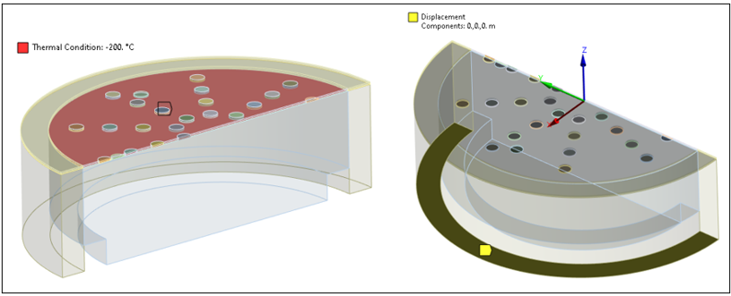
- Structural Boundary Conditions
The base of the silicon substrate is constrained in all structural degrees of freedom. Also, a temperature of -200 °C is applied to the membrane to represent the manufacturing tension prestress.
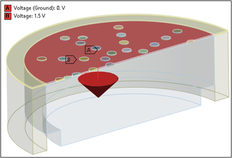
- Electrical Boundary Conditions
A DC bias voltage of 1.5 V is applied to the membrane to illustrate the variation of capacitance with bias voltage. The backplate is grounded.
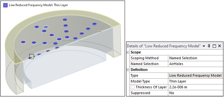
- Acoustic Boundary Conditions
The interaction between an acoustic pressure wave in a viscous fluid and a rigid wall is considered for specific structures according to the Low Reduced Frequency (LRF) approximation. The LRF Model object is specified as a Thin Layer of 2.2 μm.
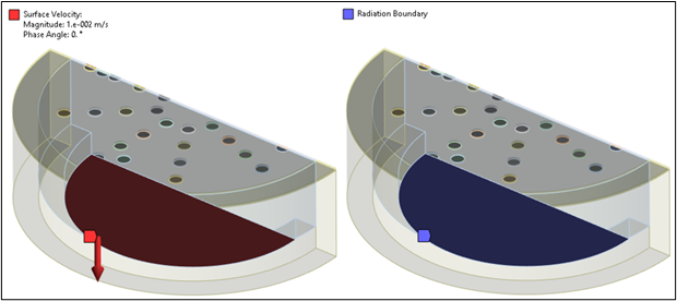
After a coupled field static analysis under structural and electrical loading (temperature and DC bias), a linear perturbation coupled field harmonic analysis is performed to analyze the response of the microphone to an incoming pressure wave. In that regard, a velocity of 0.01 m/s and an infinite radiation boundary are applied on the sound port inlet.