VM-AM-MECH-003
VM-AM-MECH-003
Additive Manufacture of 3-Inch Double Cantilever with Supports Using
Ti-6Al-4V
Overview
| Reference: | Model and experimental results courtesy of University of Pittsburgh |
| Material: | Ti-6Al-4V |
| Solver(s): | Additive in Mechanical |
| Physics/Modes: | Linked Transient Thermal - Static Structural |
| Supports Included: | Yes |
| Platform: | Windows only |
Test Case
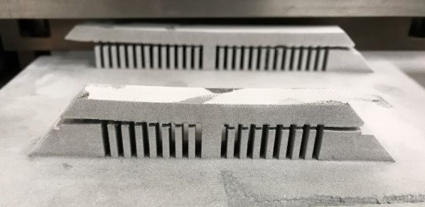
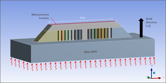
Perform a simulation of a Laser Powder Bed Fusion (L-PBF) additive manufacturing process of a 3-inch beam with cantilevered ends with supports printed with Ti-6Al-4V titanium alloy.
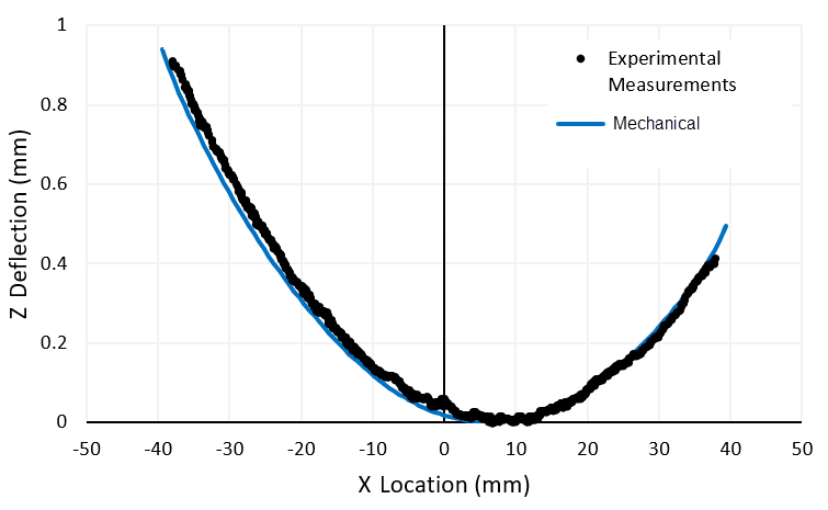
Find the Z-direction distortion along an edge of the part after the supports have been removed and compare results to measurements taken of the built part.
Analysis Assumptions and Modeling Notes
Material properties are used for EOS Ti-6Al-4V. The simulation includes a build step, a cooldown step, and support removal steps. Heat is applied at a constant temperature (35°C) to the underside of the base plate during the build step. Room-temperature convection is applied to that same surface during the cooldown step. Throughout the simulation the base plate is anchored by a fixed boundary condition on the underside of the plate. Supports are removed first from the left side (all at once) and then from the right side (all at once). Measurements are made after the supports have been removed. Deflection results were measured along the centerline of the top surface. For comparison purposes, the minimum deformation was set to zero for both the experimental and simulation data. The analysis is performed using a Cartesian mesh.
| Build Settings | Build Conditions | Cooldown Conditions |
|---|---|---|
| Deposition/Powder Layer Thickness = 0.03 mm | Preheat Temperature = 35°C | Room Temperature = 22°C |
| Hatch Spacing = 0.14 mm | Gas Temperature = 35°C | Gas Temperature = 22°C |
| Scan Speed = 1200 mm/sec | Powder Temperature = 35°C | Powder Temperature = 22°C |
| Dwell Time = 9 sec | Gas Convection Coeff = 0.00001 W/mm2°C | Gas Convection Coeff = 0.00001 W/mm2°C |
| Dwell Time Multiple = 5 | Powder Convection Coeff = 0.00001 W/mm2°C | Powder Convection Coeff = 0.00001 W/mm2°C |
| Number of heat sources = 1 | Powder Property Factor = 0.01 | Powder Property factor = 0.01 |
| Mesh and Material Settings |
|---|
| Element size = 0.7 mm Cartesian mesh |
| Projection Factor = 0.7 |
Results Comparison
The distortion in the Z direction follows the trend of the measured results. Despite the symmetrical geometry, distortion is unsymmetrical. The amount of distortion at each end is affected by the support removal sequence.
| Results | Target | Mechanical | Error (%) |
|---|---|---|---|
| Z Deformation (Positive X End) | 0.49095 | 0.51619 | 5.1410 |
| Z Deformation (Negative X End) | 0.9136 | 0.95405 | 4.4275 |