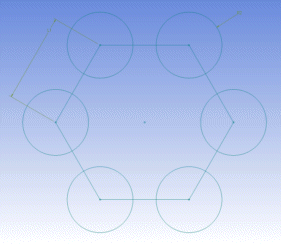
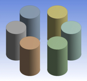
One very important use of having multiple sketches in a plane is to use one sketch just for construction geometry. You can name this sketch "Construct" or something similar to remind you that it is for construction geometry. This sketch can be used for geometry that is useful for the construction or constraints on other geometry, but is geometry that you do not wish to be included in a feature.
For example, if you want to create a circular pattern of holes, it can be difficult to constrain/dimension these so that they remain in the pattern you want, especially if you want the option of later modifying the radius of the pattern.
An easy way to deal with this is to create a construction sketch and then create a polygon in that construction sketch, with the same number of sides/vertices that you want for the pattern of holes. Then constrain/dimension the polygon so that the vertices are where you want the circle centers to be.

Finally, go back to the sketch where you want real geometry created and create the circles, with each circle center coincident with one of the polygon vertices. Now you can modify the radius of the polygon, or rotate it, and the circles will move with it. However, if you extrude the sketch with the circles, the polygon is ignored.

Another simple example is if you want a series of circle centers to be linear, you can simply create a line in a construction sketch and constrain all of the circle centers to be on that line.
Other Sketches and Planes topics:


