


The Section Plane window gives you access to the functionality for creating a cut or slice on your model so that you can view internal geometry. You can create as many as six section planes for a model. Once this maximum is met, the feature becomes disabled until less than six planes exist.
Selecting the New Section Plane button ( ) in the
Rotation Modes toolbar initiates the function and displays the Section Planes window illustrated below.
) in the
Rotation Modes toolbar initiates the function and displays the Section Planes window illustrated below.
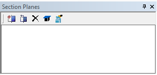
The Section Planes window provides the following capabilities.
| Icon Button | Application-Level Command |
| New Section Plane |
 | Edit Section Plane |
 | Delete Section Plane |
 | Show Capping Faces |
 | Show Capping Faces by Body Color |
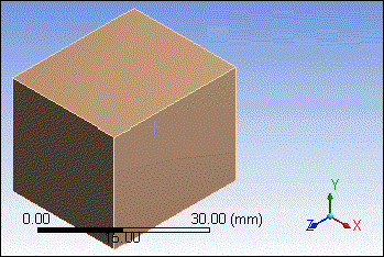
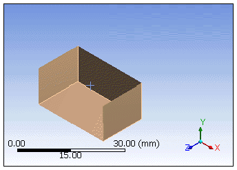
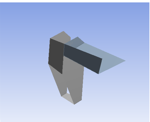
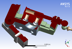
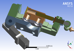
Example 6: Section Plane Example
As an example, consider the model shown below that is subjected to a horizontal and a vertical slice. Results are shown on the right.
 |  |
For additional information about the use of the Section Plane feature, see the following topics.
GUI Navigation: to add a section plane
To add a section plane:
In the Section Planes window, click the New Section Plane button.
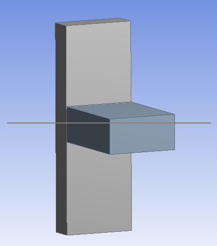
Drag the mouse pointer across the geometry where you want to create a section plane.
Note: Dragging from Left-to-Right will clip everything above the line, whereas dragging Right-to-Left will clip everything below the line.
The new section plane is listed in the Section Planes window with a default name of “Section Plane #.” The check mark next to the plane’s name indicates it as an active section plane.
You can construct up to six section planes by clicking the New Section Plane button and dragging additional lines across the model.
Note: Activating multiple planes displays multiple sections:
GUI Navigation: to use section planes
Maneuver between multiple planes by highlighting the plane names in the Section Planes window.
Unchecking a plane disables that plane.
Unchecking all the planes effectively turns the Section Plane feature off.
When viewing geometry, the cut is performed using a hardware clipping method. This hardware clipping cuts away the model in a subtractive method.
GUI Navigation: to modify a section plane
To modify a section plane:
In the Section Planes window, select the plane you want to edit.
Click the Edit Section Plane button.
The section plane’s anchor appears.
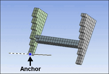
Drag the section plane anchor to change the position of the plane.
You can click on the line on either side of the anchor to view the exterior on that side of the plane. The anchor displays a solid line on the side where the exterior is being displayed. Clicking on the same side a second time toggles between solid line and dotted line, i.e. exterior display back to section display.
GUI Navigation: to delete a section plane
To delete a section or capping plane:
In the Section Planes window, select the plane you want to delete.
Click the Delete Section Plane button.
GUI Navigation: using capping faces
Capping faces are on by default and set to the body color. When enabled, it allows you to visualize the cross section for solid bodies. To change whether capping faces are shown, select the Show Capping Faces button in the Section Planes toolbar. To toggle whether capping faces are displayed in the body color or a basic red color, select the Show Capping Faces by Body Color button.
Notes regarding capping face display:
Capping faces are only displayed when a single section plane is active.
Capping faces are not displayed for bodies that have hidden faces.
Capping faces are not displayed for bodies that share topology after the Share Topology feature has been applied.
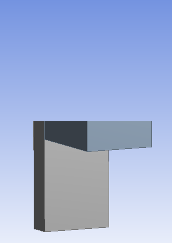
For reference, illustrated below are examples of three common states of Capping faces.
 |
| Example of no capping faces. |
 |
| Example of capping faces with red display. |
 |
| Example of capping faces with body colored display. |