


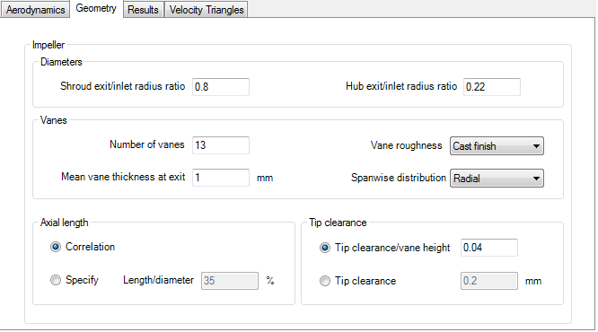
This tab contains all the required geometric input data in the Impeller frame.
Frame 1: Diameters
This frame contains the following data items:
Shroud exit/inlet radius ratio. This is the ratio of the exducer shroud radius to the impeller inlet radius.
Hub exit/inlet radius ratio. This is the ratio of the exducer hub radius to the impeller inlet radius.
Frame 2: Vanes
This frame contains the following data items:
Number of vanes.
Mean vane thickness at exit.
Vane roughness (k). The Vane roughness is only available when using the
Suhrmannstage efficiency correlation and is otherwise disabled. There are two options:Cast finish( )
)Machined finish( )
)
Spanwise distribution can be set to
RadialorGeneral. If it is set toRadial, then, if the vane geometry is exported to BladeEditor or BladeGen, all camberlines will have the same theta value at any given axial coordinate. An example of a radial element blade is shown in Figure 10.5: Contour plot of theta (θ) versus radial (R) and axial (Z) coordinates on a blade defined withRadial Element.
Frame 3: Axial length
There are two options:
Correlation. The impeller axial length will be estimated by a correlation.
Specify. You must specify the Length/diameter as a percentage.
Frame 4: Tip clearance
There are two option:
Tip clearance/vane inlet height. This is the tip clearance expressed as a ratio
Tip clearance. This is the tip clearance specified directly.