


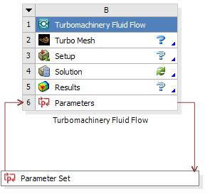
You can create a Turbomachinery Fluid Flow system, which is essentially a CFX system with an added Turbo Mesh cell, using the Create New > Turbomachinery Fluid Flow command in the right-click context menu of the Turbo Setup system’s Turbo Setup cell. The Turbo Mesh and Setup cells of the Turbomachinery Fluid Flow system are initialized with the appropriate settings as prescribed by the Turbo Setup system; the settings are applied on the first Edit, Refresh or Update of the cells. Typically a link from an upstream blade design, either from BladeGen (a BladeGen system’s Blade Design cell) or BladeEditor (a Geometry system’s Geometry cell), is made to the Turbomachinery Fluid Flow system’s Turbo Mesh cell; the Turbomachinery Fluid Flow system is simply updated to run a steady-state RANS CFD calculation for the design. The properties of the Results cell are populated from the Turbo Setup system so that the appropriate report is generated and exported as an HTML file.
In addition to an initialized system, a default set of input and output parameters is created as detailed in Figure 3.2: Parameters. This parametric approach to operating conditions is exploited when creating a performance map in order to assess the design over the entire operating range.
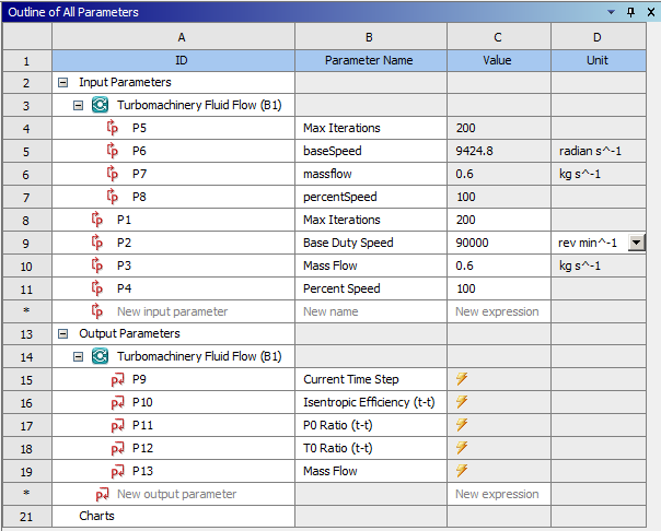
In Figure 3.2: Parameters, inputs P1 to P4 are common to any further Turbomachinery Fluid Flow systems created from the same Turbo Setup component. This enables the same operating point definitions to be used for multiple designs and compared directly on the Performance Map tab in the Turbomachinery Data Setup dialog box.
When a Turbomachinery Fluid Flow system is generated from a Turbo Setup system, an additional Reinitialize context menu command is available for the Turbo Mesh and Setup cells. When this command is issued, first the cell is reset then the initial settings that were passed from the Turbo Setup system will be re-applied. This provides a convenient way to recover the original case setup if needed.
Note: When you first edit the Turbo Mesh cell, TurboGrid appears and the geometry is initialized. If you then attempt to load a BladeGen *.inf file using the TurboGrid user interface, the geometry (which is already initialized) will not be re-initialized according to the BladeGen *.inf file. Some options for specifying the geometry are:
Link an upstream blade design to the Turbomachinery Fluid Flow system’s Turbo Mesh cell.
Reset the Turbo Mesh cell to uninitialize the geometry. You can then edit the Turbo Mesh cell and, when the TurboGrid user interface appears, you can load a BladeGen *.inf file, which will initialize the geometry. Note that this approach involves losing all Turbo Mesh cell settings that were prescribed by the Turbo Setup system; however, no Setup cell settings are lost.
Typical workflows using Turbo Setup to analyze a centrifugal compressor design with Turbomachinery Fluid Flow systems are:
Single geometry; single performance map; single TFF system
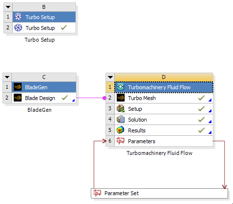
This is the most basic workflow where there is a single geometry to assess and the Turbo Setup is used to create the operating conditions and display the performance map.
Single geometry; single performance map; multiple TFF systems
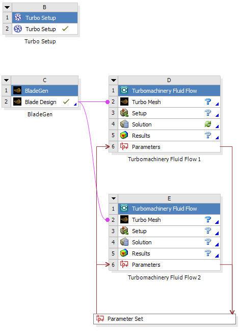
This workflow is very similar to the first but uses an additional analysis system that could, for example, use a different turbulence model. Both Turbomachinery Fluid Flow systems use the same geometry, input parameters, and operating points, but multiple sets of resulting output parameters are retrieved by the Turbo Setup system for postprocessing and comparison.
Multiple geometries; single performance map; multiple TFF systems
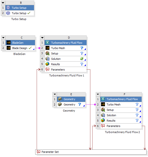
This is probably the most common scenario with each Turbomachinery Fluid Flow system using a different design. Here the different designs are compared in the Turbo Setup performance map for the same operating conditions.
It is also possible to create multiple performance maps for a project by using multiple Turbo Setup components. While this is a valid workflow, be aware that the project can quickly become rather complicated. There is little advantage in using multiple Turbo Setup components in one project. It is recommended that a single Turbo Setup system is used in each project to avoid unnecessary complexity.
Note: When using Remote Solve Manager:
If you are using custom report templates in CFD-Post, you should avoid using UNC paths (paths that begin with two backslashes rather than a drive letter) when using Remote Solve Manager. You can use one of the following methods to avoid using UNC paths:
Instead of using a shared cluster directory on the machine that has the head node of the compute cluster, set up a scratch directory on each machine that has an execution node. Each machine will then refer to its own local directory, which does not require access via a network path.
Use a shared directory on the machine that has the head node of the compute cluster. On each machine that has an execution node, map the network path to that shared directory (or any parent directory of it) as a drive letter. Use that drive letter when specifying the path to the shared directory.