


In Ansys Workbench, click File > Save As.
Save the project as
BE_tutorial1in a suitable directory.In the Toolbox pane, under Component Systems, double-click Vista CCD.
A new Vista CCD system appears in the Project Schematic pane.
If the Properties pane is not already displayed, show the Blade Design cell properties by right-clicking the cell and selecting Properties.
In the Properties pane, set BladeModeler units to
cm.When using this method, DesignModeler does not prompt for units; it uses whatever units you set here.
Leave the other settings at default values because you are using Vista CCD only to create a geometry. The focus will be on editing this geometry in BladeEditor.
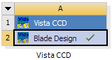
Right-click the Blade Design cell in the Vista CCD system and select Update.
After a short time, the Blade Design cell should have a check-mark as shown in Figure 10.16: Project Schematic Pane.
Right-click the Blade Design cell and select Create New > Geometry.
Over the next several seconds, a Geometry system is added in the Project Schematic pane and the geometry is created in DesignModeler.
Right-click the Geometry cell, and select Edit Geometry in Design Modeler... to launch DesignModeler.
You have created the geometry using Vista CCD and are now ready to edit the geometry using BladeEditor (which is accessed via DesignModeler).