Clicking the ![]() icon adds
an Internal Tank Pressure object to the Static Structural analysis.
icon adds
an Internal Tank Pressure object to the Static Structural analysis.
Alternatively, you can right-click the Static Structural analysis and select > from the context menu.
You can only add an Internal Tank Pressure object after a Hydrodynamic Pressure object has been added to the Static Structural analysis.
You must ensure that the number of Internal Tank Pressure objects in the Static Structural analysis is the same as the number of Internal Tanks defined in the upstream time domain Hydrodynamic Response analysis to account for the weight of the Internal Tank fluid in the force balance in the Static Structural system. Otherwise, there would be an imbalance of vertical forces resulting in an acceleration of the structure out of the water.
Note: In the Static Structural system the hydrostatic force on the external surfaces is included via the Hydrodynamic Pressure object, while the structure weight is calculated from the material properties and surface body thicknesses defined under Geometry. For the forces to be correctly balanced, the weight of the Internal Tank fluid must also be accounted for. This comes from the Internal Tank hydrostatic force (integral of hydrostatic pressure over the Internal Tank surfaces). For this reason, you must ensure that the timedomain Hydrodynamic Response model and its linked Static Structural system include the same number of Internal Tank Pressure objects.
You can configure options for the Internal Tank Pressure object in the details panel (see Figure 8.17: Details of Internal Tank Pressure).
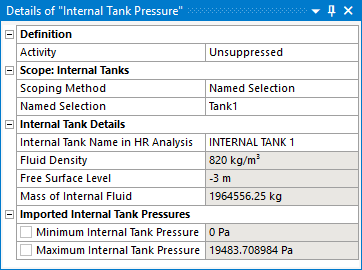
The Activity field allows you to set the suppression state of the Internal Tank Pressure object. Set it to Suppressed if you want to exclude the object from the analysis.
Use Scope: Internal Tanks to select the surfaces that you want to map internal tank hydrodynamic pressures onto. Surfaces can be selected either by Named Selection, or by Geometry Selection from the graphical window.
Once you have selected the internal tank surfaces in the Static Structural model, you must associate them with the corresponding Internal Tank in the time domain Hydrodynamic Response analysis. Internal Tank Name in HR Analysis lists the names of the Internal Tanks that are defined in the time domain Hydrodynamic Response analysis, and which are associated with the structure selected in the Hydrodynamic Pressure object. Select the appropriate Internal Tank from this list.
The Fluid Density and Free Surface Level that have been defined in the time domain Hydrodynamic Response analysis for the selected Internal Tank, as well as the calculated Mass of Internal Fluid, are displayed for reference.
In some instances the internal tank pressures shown in the graphical window may be out of date. In this case, the Refresh Graphical Window option will appear, in an invalid state, and should be changed from Required to Not Required. The option will then disappear, and the state of the Internal Tank Pressure object will change to show that it requires an update. Right-click on the Internal Tank Pressure object and select Generate to display the correct internal tank pressures.
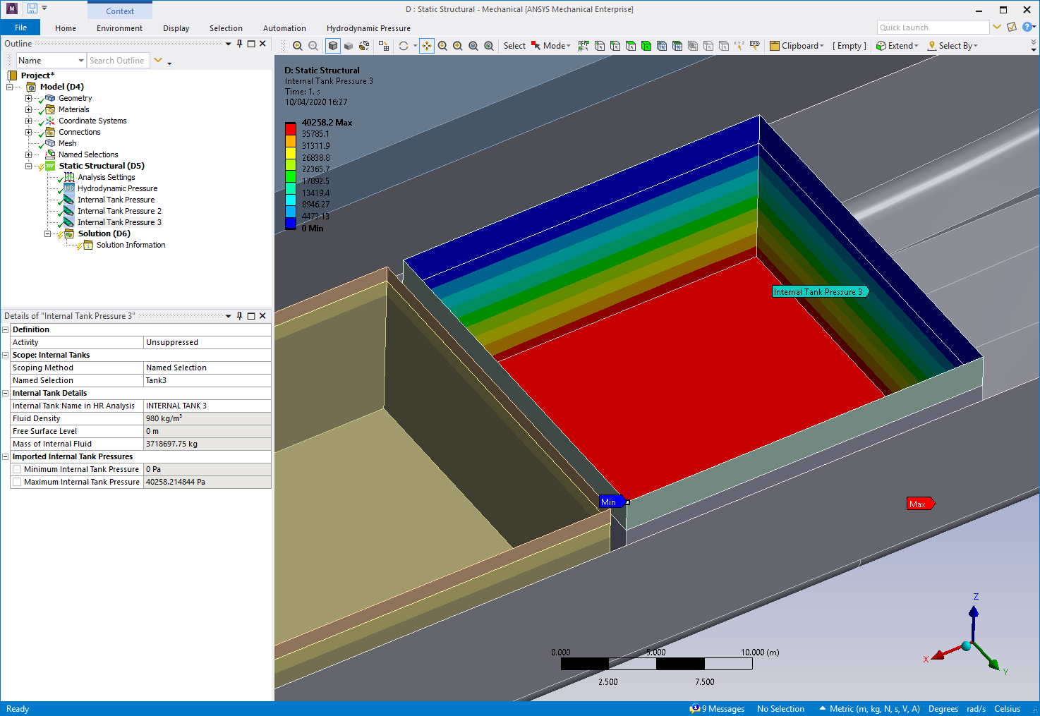
Once you have Generated the Internal Tank Pressure object, the Minimum and Maximum Internal Tank Pressures on diffracting panel elements are reported. Where applicable, values are displayed for the time step selected in Display for Time Step as defined in the associated Hydrodynamic Pressure object.
Once the Internal Tank Pressure object has been configured, right-click on it and select Generate to start the pressure transfer process. The time step(s) for the pressure transfer process are copied from the Hydrodynamic Pressure object:
The output data files from the time domain Hydrodynamic Response calculation will be read to determine the internal tank hydrodynamic pressures at the structural mesh nodes for the requested time step(s).
Note: The Hydrodynamic Pressure Add-on will take into account any difference in the unit systems that are employed in the time domain Hydrodynamic Diffraction and Static Structural systems.
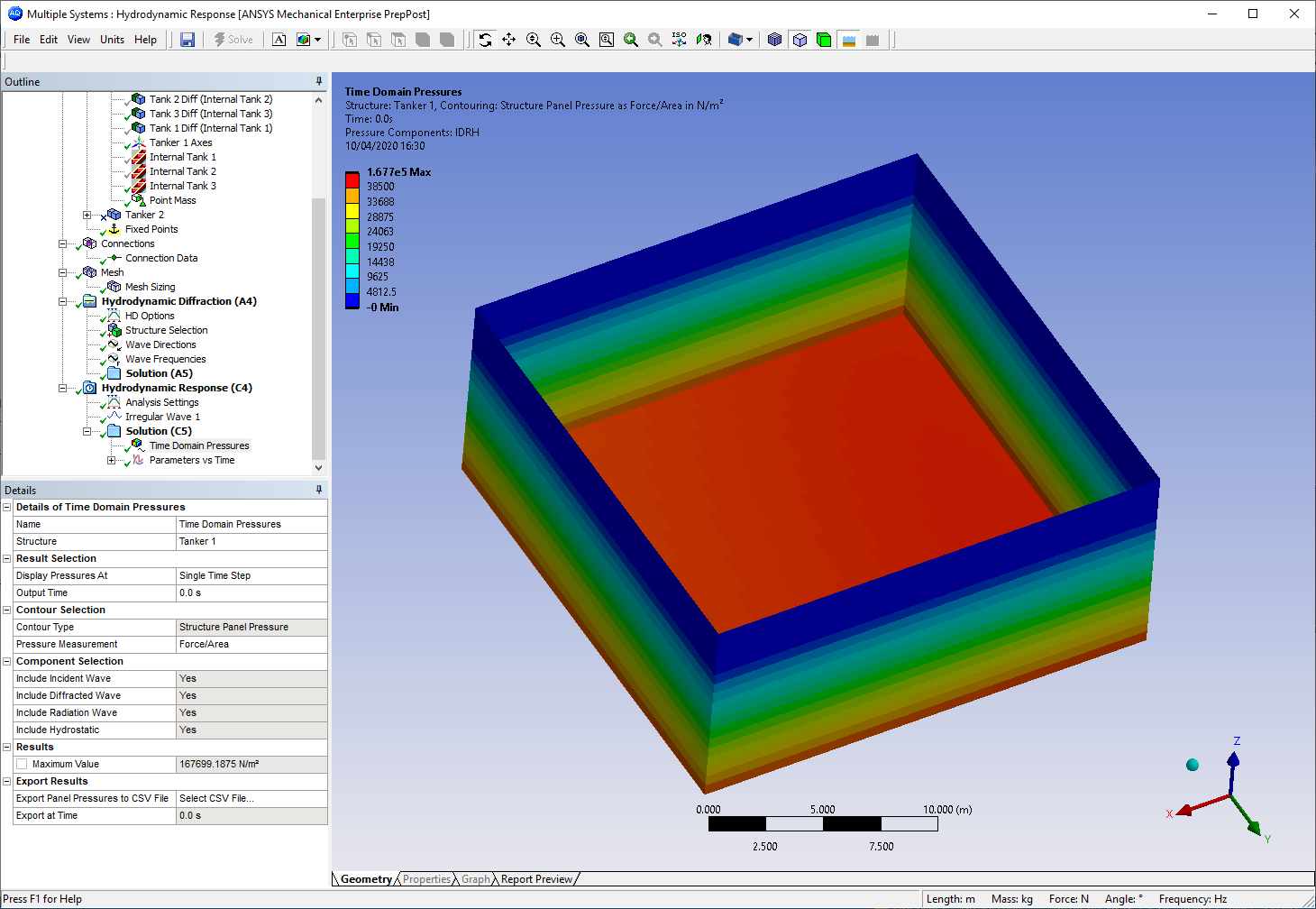
The transferred pressures are displayed in the graphical window (Figure 8.18: Internal Tank Pressures in the Static Structural System), and can be compared to the Internal Tank Panel Pressures (Figure 8.19: Internal Tank Pressures in the Time Domain Hydrodynamic Response System) shown in the Time Domain Pressures result object in the upstream time domain Hydrodynamic Response system.