Clicking the ![]() icon will add a
Cable Force object to the Static Structural analysis.
icon will add a
Cable Force object to the Static Structural analysis.
Alternatively, you can right-click the Static Structural analysis and select > from the context menu.
You can only add Cable Force objects after a Hydrodynamic Pressure object has been added to the Static Structural analysis.
You must ensure that the number of Cable Force objects in the Static Structural analysis is the same as the corresponding number of Cables attached to the selected structure in the upstream time domain Hydrodynamic Response analysis. Otherwise, there would be an imbalance of forces resulting in an acceleration of the structure in the Static Structural analysis.
You can configure options for the Cable Force object in the details panel (see Figure 8.21: Details of Cable Force).
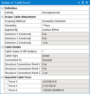
The Activity field allows you to set the suppression state of the Cable Force object. Set it to Suppressed if you want to exclude the object from the analysis.
Use Scope: Cable Attachment to select the topology that you want to map cable forces onto. Topology can be selected either by Named Selection, or by Geometry Selection from the graphical window. Cable forces can be mapped on to one or more faces, edges, vertices, mesh nodes or mesh element faces.
When the topology selection type is faces or mesh element faces, the Applied By option can be used to apply the imported force by Direct or by Surface Effect approach. The Surface Effect option applies force using the surface effect elements created on the top of the scoped geometry. The Direct option applies force directly onto the faces of solid or shell elements in 3D analyses.
Once a topology selection has been made, the Selection X/Y/Z (Centroid) is reported and should be checked against the Structure Connection Point X/Y/Z position displayed in the Cable Details section.
Note: A warning will be issued if there is a significant difference between the selection centroid and the connection point position in the hydrodynamic model.
Once you have selected some topology in the Static Structural model, you must associate this with the corresponding Cable in the time domain Hydrodynamic Response analysis. The Cable Index in HR Analysis option lists the indices of the Cables that are defined in the upstream time domain Hydrodynamic Response analysis, and which are attached to the structure selected in the Hydrodynamic Pressure object. Select the appropriate cable index from this list.
Note:
In the upstream Hydrodynamic system, when you select the Connections object in the Outline tree, a Hydrodynamic Response Connections Summary table will be displayed. This allows you to associate the connections in the hydrodynamic model with their corresponding indices in the analysis.
For a cable in the upstream Hydrodynamic system that includes at least one pulley attachment, each cable length between the attachments is assigned its own cable index. Where both attachments for a given cable index are located on the structure selected in the Hydrodynamic Pressure object, the Cable Index in HR Analysis menu will include an option to select either the First or Second Attachment.
Once a cable index has been selected, the Structure Connection Point X/Y/Z definition position will be displayed for reference. The position is transformed into the Static Structural axis system, using the Axis Transformation defined in the Hydrodynamic Pressure object.
Also displayed is the Cable Type, which is either ‘Linear’ or ‘Nonlinear’, depending on the definition in the hydrodynamic model; and Connected To, which will show ‘Ground’ for a cable between a structure and a Fixed Point, or displays the name of the other structure in the Hydrodynamic Response analysis for a cable between two structures.
In some instances, the imported forces shown in the graphical window may be out of date. In this case, the Refresh Graphical Window option will appear, in an invalid state, and should be changed from Required to Not Required. The option will then disappear, and the state of the Cable Force object will change to show that it requires an update. Right-click on the Cable Force object and select Generate to display the correct imported forces.
Once the Cable Force object has been configured, right-click on it and select Generate to start the force import process. The time step(s) for this process are copied from the Hydrodynamic Pressure object, which must be Generated first.
The output data files from the time domain Hydrodynamic Response calculation will be read to determine the cable forces for the requested time step(s).
Note: The Hydrodynamic Pressure Add-on will take into account any difference in the unit systems that are employed in the time domain Hydrodynamic Diffraction and Static Structural systems.
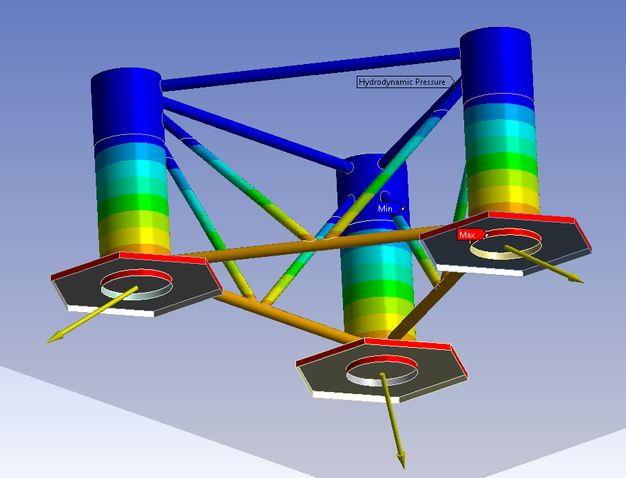
The transferred cable forces are displayed as yellow arrows in the graphical window (see Figure 8.20: Imported Forces in the Static Structural System).