


If the external Mechanical Mesh component is part of your workflow on the Workbench Project Schematic, you will find that the Aqwa Workbench Mesh object is read-only, and any changes to the mesh must be made in the upstream Mesh component.
If you have imported an Aqwa input file using the operation, and there are no other active Parts in the model, then the Aqwa Workbench Mesh object is read-only. There is no function to modify the mesh imported from an Aqwa input file, currently.
Otherwise, the options in the Details panel of the Aqwa Workbench Mesh object are applied to all unsuppressed Parts and Bodies in your model. Local Mesh Sizing objects can be added to override the global Mesh settings on selected Parts or Bodies.
Mesh elements are not generated for any suppressed Parts or Bodies, and they will not appear in any mesh-based results such as Pressures and Motions, Internal Tank Pressures, or Time Domain Pressures.
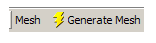
To generate the mesh:
Select the object in the tree.
Right-click or click the button from the toolbar.
Note: It is not yet possible to employ symmetry in Aqwa, hence the full model must be meshed.
The mesh controls available in the Aqwa Workbench editor are described in the following sections:
Once a mesh has been generated successfully, the section shows the Total Nodes and Total Elements in the mesh. These totals do not include elements that are generated by the Aqwa solver when a Part's Generate Internal Lid option is set to Program Controlled. By default, the Graphical window displays the mesh nodes and elements in a simple grey tone:
If you change the Display Mesh Metric option from None to Element Types, the Generated Mesh Information shows the breakdown of nodes and elements into:
External Surface Diffracting Nodes
External Surface Diffracting Elements
External Surface Non-Diffracting Nodes
External Surface Non-Diffracting Elements
Internal Tank Diffracting Nodes
Internal Tank Diffracting Elements
Internal Tank Non-Diffracting Nodes
Internal Tank Non-Diffracting Elements
Abstract Lid Nodes
Abstract Lid Elements
Line Body Nodes
Line Body Elements
Field Points
Moonpool Wall Surface Diffracting Nodes
Moonpool Wall Surface Diffracting Elements
Moonpool Wall Surface Non-Diffracting Nodes
Moonpool Wall Surface Non-Diffracting Elements
Moonpool Free and Matching Surfaces Nodes
Moonpool Free and Matching Surfaces Elements
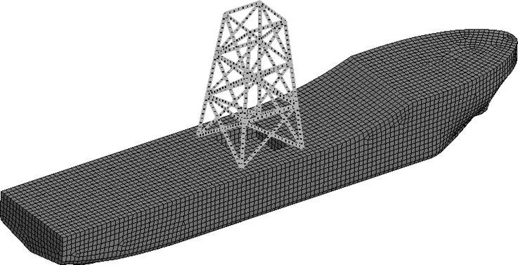
In the Graphical window, the elements are colored according to their type:
If you change the Display Mesh Metric option to Failing Panels, the Generated Mesh Information will display the Diffracting Element Minor Failure Rate. This is the percentage of diffracting panel elements that fail the mesh quality checks described in Mesh Quality Check, but whose failures can be avoided by turning on the Ignore Modeling Rule Violations option in the Hydrodynamic Diffraction Settings. Generally, it is recommended that this percentage must be as small as possible. Reducing the Element Size usually helps, though naturally, this also increases the computational cost of the hydrodynamic analysis.
The Details panel also shows the breakdown of panel failures into:
Aspect Ratio Failures – where the aspect ratio of an element is less than 0.333
Adjacent Element Area Ratio Failures – where the area ratio of adjacent elements is greater than 3
Shape Factor Failures – where the shape factor of the element is less than 0.2
Centroid Proximity Failures – where the distance between a pair of elements in the same interacting group is less than the effective radius of either of those elements
Centroid Proximity Failures (FATAL) – as above, but with a stricter limit of 0.1x effective radius
Element-Seabed Proximity Failures (FATAL) – where a diffracting element is less than half of its effective radius above the seabed
Mesh Connectivity Failures (FATAL) – where an element edge is shared by more than two elements (so-called ‘T’ connectivity)
Elements Cutting Fluid Surface (FATAL) – where diffracting elements cross the waterline or Internal Tank fluid level, as applicable
Note: A field is not shown in the Details panel if there are no elements failing for that mesh quality check. You will not be able to run the Hydrodynamic Diffraction analysis if there are any fatally-failing elements in the mesh.
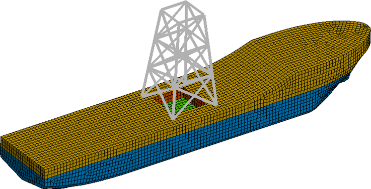
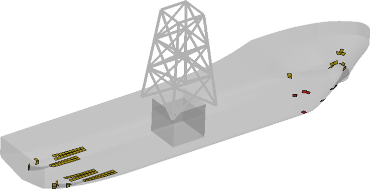
In the Graphical window, the elements suffering minor quality check failures are displayed in orange, while fatally-failing elements are shown in red, and all other elements are shown as transparent:
Note: By default, the mesh information is displayed for all active Parts. However, where there are multiple active Parts in the Geometry, use the option to display mesh information for a single Part.