


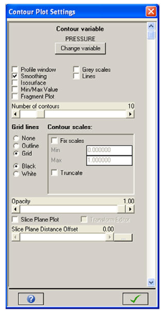
This panel lets you set the following options for contour plots (some options are not present for 2D models):
- Contour variable
Click Change Variable to open the Select Contour Variable dialog window, allowing you to choose the variable you want to contour.
- Profile window
Opens the Profile Plot dialog window, allowing you to compose and display a profile plot.
This option is only available for structured solvers.
- Smoothing
Smooths contour plots. All elements have a single centered value for each variable. If you do not smooth a contour plot each element will be color-coded for the value the variable has in that element. If you smooth a contour plot, then the centered values are interpolated in space to provide smoothly varying values.
- Isosurface
View a 3D isosurface plot of the contour variable. You are prompted for the value to be used for the plot.
- Min/Max Value
Open a window that displays the minimum and maximum values for the contoured variable.
- Grey scales
View contour plots using grey scales instead of color.
- Lines
View contour plots with colored lines instead of colored fills.
- Number of contours
The number of contours you want to use for your plot.
- Grid lines
View grids with or without grid lines (or with just the outline of the grids displayed) and set the color in which the grid lines or outline are displayed.
- Contour scales
Usually you should let the maximum and minimum values between which contours are plotted be set automatically using the data in the model. However, you may override these settings in the Contour scales box. For example, if a maximum value is entered which is lower than the highest value present in the model, a red area will appear corresponding to all values above the maximum that has been set. Selecting Fix scales lets you fix the current maximum and minimum values. This is particularly useful when you want to generate a slideshow from multiple cycles of a single model. The red area may be removed by selecting Truncate.
- Opacity
The opacity for your view. An opacity of 1.0 means you cannot see inside the grid. An opacity of 0.0 is equivalent to turning hidden line removal off (that is, you can see everything inside the grid).
- Slice Plane Plot
The "Slice Plane" feature is a visual tool to take a section through a model at an arbitrary angle. Results values, as selected under the contour option, are contoured on the selected slice through the model.
We recommend that you use the slice box feature in conjunction with the Opacity feature of the Contour plot to obtain best results.
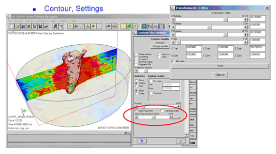
Example slice plane plot showing the damage inside a concrete target.