


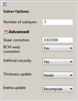
- Number of sublayers
Specify the number of through thickness integration points for an isotropic shell. The default of 3 is suitable for many applications however this number can be increased if better resolution of through thickness plastic deformation/flow is required.
The following advanced options are also available. Note these are not intended for general use.
- Shear correction factor
The transverse shear in the element formulation is taken as constant over the thickness. The correction factor accounts for the replacement of the true parabolic variation through the thickness by a uniform transverse shear stress. We do not recommend that you change the default value.
- BCW warp correction
The Belytschko-Lin-Tsay element formulation becomes inaccurate if the elements are warped. To overcome this shortcoming, the element formulation has a correction for the element warp included. We recommend that this correction is turned on.
- Artificial Viscosity
Choose whether to apply artificial viscosity to compression waves in the shell. The values for the quadratic and linear coefficients and whether to use the linear term in the expansion come from the global settings for artificial viscosity which can be found under the Damping Options in the Controls menu.
- Thickness Update
By default the thickness of a shell quad element is stored and updated at the nodes of the element. An alternative, slightly more efficient, option to store and update the thickness at the element is also provided. The thickness of a shell tri element is always updated at the element irrespective of the settings for Shell Thickness update in Autodyn.
- Inertia Update
The principal axes of rotary inertia for shell elements are, by default, recalculated each cycle. Alternatively, there is an option to rotate the axes, rather than recompute each cycle. This latter option is more efficient, however can lead to instabilities.