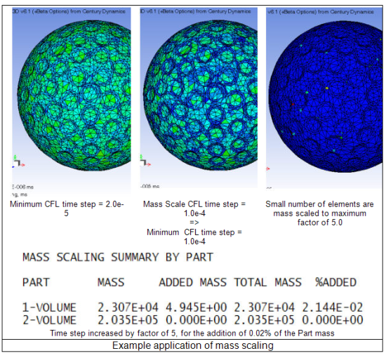
Mass scaling is an artificial (numerical) mechanism for increasing the CFL (Courant-Friedrichs-Levy) timestep of individual elements that govern the maximum allowed timestep of explicit transient dynamic solutions in Autodyn. Increasing the timestep has the obvious benefit of reducing the number of cycles required to run a simulation to a given point in time. Educated use of this option can therefore result in significant improvements in efficiency.
The primary use of mass scaling is to increase the CFL timestep of a small number of very small (or stiff) elements in the model, which otherwise would have controlled the timestep for all elements. Using this option, Autodyn will automatically add artificial mass to individual elements to ensure that their CFL timestep is at least equal to a value defined by you. Mass scaling should only be used if the increased inertia of the scaled elements does not significantly affect the results of the simulation.
Mass scaling can also be used to increase the CFL timestep of elements that become highly distorted during the simulation. Extreme care should be taken to ensure that results obtained remain physical.
Mass scaling is activated under Controls, Timestep and the input parameters are defined as follows:
- Automatic Mass Scaling
Activate automatic mass scaling.
- Frequency (cycles)
Cycle frequency that Autodyn will adjust the element mass scaling (this is not supported in parallel solutions). Recommended default is only at start-up (cycle 0). Post cycle 0 adjustment will only take place for solid elements (excluding ANP and NBS tetrahedra).
- Min. CFL timestep
Mass scaling is applied to all elements with a CFL timestep less than the specified value.
- Max. element scaling
Maximum mass scaling factor that can be applied to an element. Default is 100 (equating to 100 times original mass). If this limit is exceeded, no more mass is added to this element.
- Max. part scaling
Maximum added mass that is allowed for an Autodyn Part, as a fraction of the original Part mass. Default is 0.05 (equating to 5% of the original mass. If this value is exceeded, the simulation will terminate with an error message.
Two new element variables have been introduced with the development. These variables are automatically activated when mass scaling is selected:
TIMESTEP
The CFL timestep for the element
MASS.SCALE
The mass scale factor applied to the element. (1.0 indicates zero added mass, 2.0 indicates 100% added mass etc.)
A typical procedure to invoke mass scaling would be as follows
Activate mass scaling retaining all the default parameters
Run the simulation for 1 cycle
Plot a contour of Timestep and review the element CFL timesteps. Identify a suitable timestep for mass scaling. The value chosen should exclude the majority of elements from mass scaling, and especially those in regions critical to the simulation results
Re-load cycle zero
Enter the selected Min CFL Timestep under Controls, Timestep
Run the simulation

Important notes and limitations:
Mass scaling will only be applied to Unstructured Elements/Parts
Mass scaling is only applied to elements filled with materials which use a Linear or Hyperelastic equation of state
The actual timestep used in a simulation will generally be lower than the Min CFL timestep you define
A safety factor is applied to get the actual timestep (default = 2/3)
The timestep used at cycle 1 of the simulation is additionally reduced by a factor of 2. The timestep is then allowed to increase by a maximum of 10% per cycle.
Large velocities can affect the timestep at cycle 0
Other features of the code will influence the timestep, such as artificial viscosity, blending, Gap contact.
For Beams and Tet ANP elements, the minimum CFL timestep will be increased by using mass scaling. However, due to nodal averaging of some quantities that influence the timestep, the actual user defined CFL timestep may not be achieved.
A summary of the contribution of mass scaling applied to the model can be obtained through
Plotting a contour of variable Mass Scale. This is a ratio of current mass to original mass (with scaling).
Review the .prt file output activated using Output, Print, Energy Summary


