Welding Symbols
You can insert Welding Symbols into your design, drawing sheet, or 3D markup slide. They can be created with or without geometry in the design window.
Symbols can be made to either the AWS or ISO standard.
- AWS follows the specification titled "AWS A2.4:2007 Standard Symbols for Welding, Brazing, and Non-Destructive Examination."
- ISO follows "ISO 2553:1992 (E) Welded, Brazed, and Soldered Joints - Symbolic Representation on Drawings - p.193 of ISO Drawings."
SpaceClaim defaults to the AWS standard. You can change this in the Annotation options in the Detailing>General section of SpaceClaim options. The setting is independent of the standard chosen for font.
The basic procedure for creating Welding symbols is to build up the symbol, adding progressively more detail while the UI adapts intelligently based on your choices. There are tooltips available for every possible input value or symbol. Box-selecting the entire symbol will show all possible places to input values. Weld symbols can be created and edited while in the Welding Symbol tool.
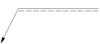
The image below shows a blank welding symbol. As you move the cursor over the highlighted areas, tooltips will guide you in building the symbol.
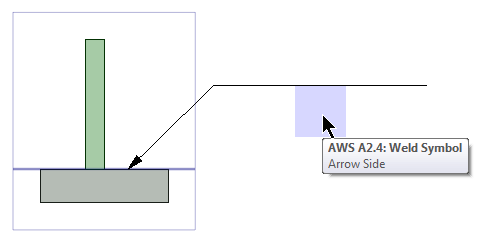
Welding symbols have an Arrow side and an Other side. The Reference line divides the symbol into the Arrow Side and the Other Side. In AWS, the Arrow Side is always on the bottom of the Reference line. In ISO, the Arrow Side is identified by a dotted line as shown in the image below.