Creating a Welding Symbol
- As you move the cursor over the symbol, highlighting will indicate where you
can add symbol elements or input values.
To build up the symbol, click either the Arrow Side or the Other side box to display the symbol palette (see images and details below).
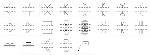
- AWS Symbols
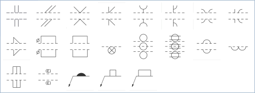
The AWS symbol palettes are shown below. Some symbols are only available for Arrow side.
Arrow Side
Other Side
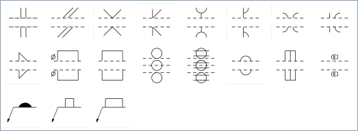
The symbols are described in the following table.
AWS Symbol Weld Type AWS Symbol Weld Type 
Groove square 
Stud 
Groove scarf 
Spot or projection 
Groove V 
Seam 
Groove bevel 
Back or backing 
Groove U 
Surfacing 
Groove J 
Edge 
Groove flare V 
Joint geometry not specified, groove weld size specified 
Groove flare bevel 
Melt-through 
Fillet 
Consumable insert square 
Plug 
Backing rectangle 
Slot - ISO Symbols
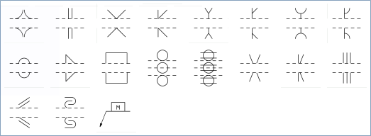
The ISO symbol palettes are shown below. Some symbols are only available for the Other side.
Arrow Side
Other Side
The symbols are described in the following table.
1.3*ISO Symbol Weld Type ISO Symbol Weld Type 
Butt weld between plates with raised edges 
Spot weld 
Square butt weld 
Seam weld 
V butt weld 
Steep-flanked single-V butt weld 
Bevel butt weld 
Steep-flanked single-bevel butt weld 
V butt weld with broad root face 
Edge weld 
Bevel butt weld with broad root face 
Surfacing 
Bevel butt weld (parallel or sloping sides) 
Surface joint 
J butt weld 
Inclined joint 
Backing run: back or backing weld /USA/ 
Fold joint 
Fillet weld 
Backing strip 
Plug weld: plug or slot weld /USA/
- AWS Symbols
-
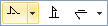
Click the Reference line to display the Reference line mini-toolbar (see images
and details below).
Symbol Option Stagger intermittent welds Weld all around 
Field weld 
Swap arrow and other sides 
Joint with spacer 
Show tail even if reference is not used 
Add welding reference line 
Add welding symbol leader -
Click the Tail text box to enter a specification process or other
reference. If there is no reference, the tail will be omitted. You can
choose to show the tail regardless of reference by clicking on
Show tail even if reference is not used .
-
Click the Tail text box to enter a specification process or other
reference. If there is no reference, the tail will be omitted. You can
choose to show the tail regardless of reference by clicking on
Show tail even if reference is not used
-
Selecting symbols after they are placed will display the symbol mini-toolbar,
which contains options to:
Open the symbol palette and change the symbol
Add secondary symbols appropriate for the selected symbol. For example, a backing symbol can has the option to add a Removable backing symbol
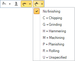
Add contour symbols for (left to right): No contour symbol, Flush or flat, Convex, Concave
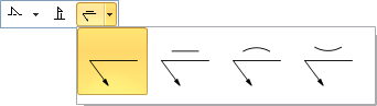
If you add a Contour symbol, you can add a Finishing symbol for: No finishing, Chipping, Grinding, Hammering, Machining, Planishing, Rolling, Unspecified