


Inserting a Standard Hole
The Hole Toolbar opens. Groups in the toolbar contain the options and inputs for hole definition.
Set options and enter values to define the hole.
Choose a Series, Size, and Fit.
The Series you choose determines the available sizes and Fit options
Choose treatments:
Blind depth
Tapped thread depth
When Tapped is checked, diameter displays tap drill size
When Tapped is checked, Fit is disabled
May be determined by Series and Size. If so, you can still enter a different value. The value you enter will be displayed in bold font to indicate it is non-standard
Default thread depth is twice the basic hole diameter
Note that only the most common Standard Hole sizes have cosmetic display
Cosmetic threads appear in the Structure tree and can be toggled on/off
Cosmetic thread depth
Cosmetic threads are only available for the UNC series
Cosmetic threads show a thread helix without actual thread geometry

Cosmetic Threads are created blind, regardless of whether the option is checked or not.
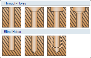
Thread depth is controlled with the Depth option in the Treatment group. To make threads go through all of the material, enter a Depth that is greater than the material depth.
- Choose a Style: Countersink, Counterbore, or both
Countersink Counterbore Both


Diameter and Angle
Determine countersink depth
Some Series specify both dimensions, some specify one, and others specify none
If they are specified, you can still enter a different value but it will be displayed in bold font to indicate it is non-standard
Diameter and Depth
Some Series specify both dimensions, some specify one, and others specify none
If they are specified, you can still enter a different value but it will be displayed in bold font to indicate it is non-standard
For Blind holes, you can specify a Drill point
Enter a Drill point angle
Choose Drill point depth measurement type
Depth to Shoulder

Depth to Tip

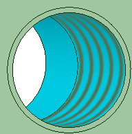
Preview shows the hole profile based on current selections and values. Shown below is a Blind, Tapped, Countersunk, and Counterbored hole with Drill point details.

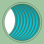
As you work with different inputs, Preview gives visual feedback. Below are examples of what you would see when entering values for Diameter, Hole Depth, Countersink Angle, and Drill point Angle.


Preview also has a gallery of profiles to choose from. Click the Preview image to open the gallery.
The gallery is a graphical way to define the hole. Selecting a hole from the gallery automatically fills in the details in the ribbon.
Choose a tool guide for hole placement.
 Snap to Grid
Select a face on which to display the sketch grid. As you move the cursor, the hole center will snap to the grid points.
 Free Placement
Pick anywhere on any face to locate the hole center.
Place the hole by clicking in the desired location.
You can continue to place this type of hole at more locations, or you can change values and options to place different types of holes.
All holes show in preview until you decide to complete them.
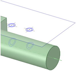
You can place holes using a plane that is some distance away from the face. This is useful if the hole must be on a curved face.
While the holes are previewed, you can:
Ctrl+click a hole preview to remove it from the set of holes to be created.
Press the Escape key to clear all previews without exiting the tool.
Complete the hole(s) by clicking
 Complete. All previewed holes will be completed.
You can also double-click when you place a hole to complete it.
Complete. All previewed holes will be completed.
You can also double-click when you place a hole to complete it.Continue to make more holes or leave the Hole toolbar.
Click in the Close group to close the toolbar.