Converting a Solid to Sheet Metal
- Click
 Convert in the Import group on the Sheet Metal
tab.The Select Bodies tool guide is enabled by default.
Convert in the Import group on the Sheet Metal
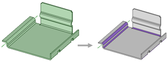
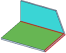
tab.The Select Bodies tool guide is enabled by default. - Select the body you want to convert.You can Ctrl+click to select multiple bodies.Walls, bends, and junctions (only default-sized junctions you created as sheet metal, not imported junctions) are automatically detected and identified by color. Faces that are not separated by the default thickness are not highlighted. Edges shown in red indicate end faces that are not square, as shown in the following figure.
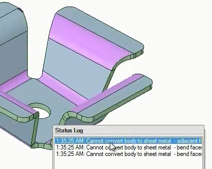
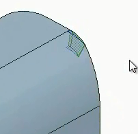
When you convert to sheet metal, faces that have problems are identified with error messages in the Status Log. Clicking on each message will highlight the problem with red blinking. In the example below,the message is selected and the problem is highlighted in the upper left corner of the leftmost image. A detailed view of the problem geometry is shown below in the rightmost image.
This example shows the converting of a sheet metal design with bends automatically detected.