


Unfolding a Component
- Select a face of a sheet metal component with at least one bend
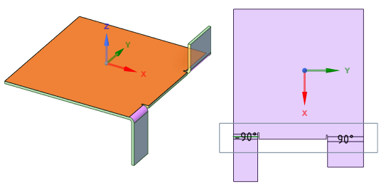
junction.When you select a single face of a sheet metal part, the Unfold tool is enabled. You can also right-click and select Unfold Part from the context menu.Note: The selected face sets the orientation of the unfolded design. Bend angle signs are related to the referenced face selected for unfolding.In this example, when the top face is selected, the bend angle is positive for the upward bends.
 If the bottom face is selected, the bend angle is negative for the upward bends.
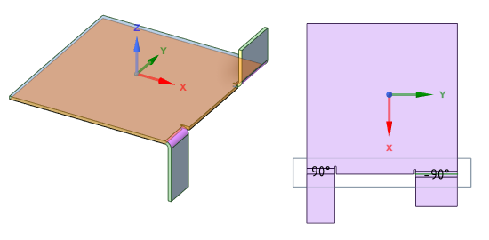
As the unfolded parts can be viewed from the top or bottom direction in drawings or unfolded views, the bend annotations in the unfolded view may or may not be in the same direction as the drawing view direction. Verify the bend angle with the referenced face to ensure proper bend orientations.
-
Click Unfold in the Flat group on
the Sheet Metal tab.
Note: Conical bends that are not exactly conical will flatten approximately.An unfolded version of the component is displayed in a new Design window as a top view with its overall dimensions, as shown in the figure below. It also appears in the Structure tree as an unfolded part
 . The
visibility of the unfolded part in the original design is initially set to Off
in the Structure tree. The unfolded part is saved as part of your design.
. The
visibility of the unfolded part in the original design is initially set to Off
in the Structure tree. The unfolded part is saved as part of your design.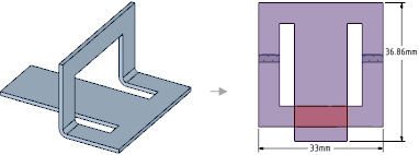
- Overall dimensions on an unfolded part are measured based on the orientation of the sketch grid. The inside angle of a bend is used to calculate dimensions. The two flat extent dimensions are automatically displayed.
- Bends are listed as objects in the Structure tree for the unfolded part. Bend lines and bend dimensions are placed on a Bends layer with the visibility off. Turn the visibility on in the Layers panel to view the bend lines.
- If a chamfer is recognized as a form, it unfolds based on the Flatten form as value in the Sheet Metal section of the Properties panel for the design.
- If an unfolded component has conflicting geometry, the conflicting geometry is made a separate surface in the Structure tree and highlighted in red, as shown in the figure below. The edge that prevents the unfold is also highlighted.
- If you save an unfolded sheet metal part within a component, opening that component in an assembly displays a check box and icon for the unfolded part in the Structure tree. You can toggle the visibility of the unfolded sheet metal part in the unfolded part design window.