A beam is a long, thin object with a constant cross-section. Defining objects as
beams, rather than modeling them as solid geometry, simplifies the model and
analysis.
- Create objects to define the beam path.
One or more of the following
methods can be used in the same design:
Sketch curves: Use any of SpaceClaim's sketching tools to create straight or curved segments and then
assign beam profiles to them. These sketch curve beams can then be
modified just like any curve in SpaceClaim
using the Move, Pull, Select, Scale, Bend, Extend, and Trim tools.
This method is a straightforward, lightweight way to create beam
structures.
Edges of a solid or surface: Use this method when you have
solid geometry that you want to reference for the beams. For
example, to create a simple rectangular cage of beams, sketch a
rectangle, pull it into a solid, and assign beams to all of the
edges.
Two points or midpoints in a model: You can use any two
points in a model to define a straight beam segment. Planes can be
used to create "stages" or additional locations for defining beams
to or from. A beam can be created to the intersection point of any
plane with any edge.
- Click
 Profiles in the Beams group on the Prepare tab.
This tool enables you to add a profile to your structure.
- Select a profile from the library or click More
Profiles to load a profile that is saved as an SCDOC
file.
Note: More than one beam can reference the same profile, so the
characteristics of all beams that use that profile will change if you
edit the profile.
- Click
 Create in the Beams group on
the Prepare tab.
Create in the Beams group on
the Prepare tab. The
Create tool is enabled when you select a profile,
which adds the profile to your design document. This tool enables you to
create the beam path.
- Select edges or points to define the path:
Click the Select Point Chain tool guide and
then select an edge or curve, or select a series of points to create
the path.
Click the Select Point Pairs tool guide and
then select a beginning and end point for the path.
You can
use intersection points and midpoints on edges and other beams.
Click the small triangles on the ends and midpoint when you hover
over an edge or beam.
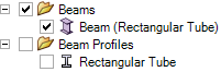
A Beams folder is created for the beams and a Beam
Profiles folder is created for the profiles in the Structure
tree:
The profile name is displayed in parentheses after the beam name in the Structure
tree.
If you have already modeled the beam you can convert it to a beam object. See Extracting a beam from a
solid.