


Basic Defaults
| Thickness |
Type a value for the default wall thickness of sheet metal parts. |
|
| Bend Table |
Specify an existing Bend Table as the default for new parts. |
|
| K-Factor (for R=T) |
Type a value for the K-factor. The K-factor is a value between .25 and .50 that is used to calculate the bend radius. K-factor is a percentage of the metal thickness and depends on factors such as the material and type of bending operation. |
|
| Bend radius |
Type a value for the default bend radius. The value is a Thickness ratio by default, but you can select Value to enter an absolute value. |
|
| Split face gap |
Set the default gap created when you bend a split face, which is shown as C in the image below. 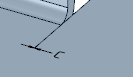
|
|
| Junction gap |
Set the default gap created in Full, Partial, and No Overlap Junctions and Flanges. Use
|
|
| Junction overlap |
Set the percentage of overlap in Partial Overlap Junctions. The default is 50%. For individual Partial Overlap Junctions, you can change the Overlap Proportion property in the Sheet Metal properties panel with the Junction selected. |
|
| Bend annotations |
Set the format for displaying Bend Annotations in the Unfolded part. |
|
| +/- Angle | 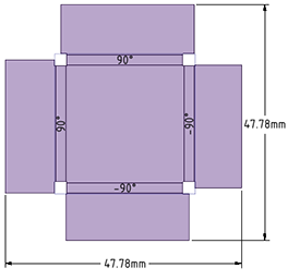 |
|
| +/- Angle Radius | 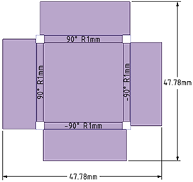 |
|
| Up/Down Angle | 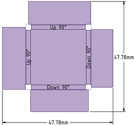 |
|
| Up/Down Angle Radius | 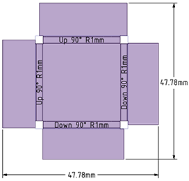 |
|
|
Note: When the Bend Radius is set to
Thickness ratio and you change the sheet metal part
thickness for the part, the value for the Inner
Radius now changes in the Sheet Metal
Properties panel. Changing the part thickness
property will not change all the bend radii, but the
displayed bend radius changes to show that there is a
problem for you to fix. You can fix them by selecting the
desired bends and changing their properties manually.
|
||
| Trim bend lines to part outline |
Controls whether Bend Lines extend beyond the Unfolded part outline. OFF by default. When unchecked, the lines extend beyond the outline. 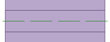
When checked, the lines are trimmed at the part outline. 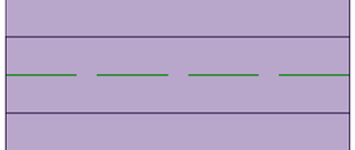
|
|