


Importing: Supported File Types
Discovery
.dsco
The Discovery files are imported using a translator. A full data match may not be guaranteed in all cases as some data may not be transferred during import.
If the model contains simulation data from Discovery, the Physics objects and existing simulation data will be removed and will be lost when the model is saved.
ACIS
Up to 2021 1.0
3D - parts, assemblies
.sat, .sab, .asat, .asab
When you save an SAT file to an X_T file, bad edges are cleaned up in the design.
When you import ACIS files, the instance name "part n (body m)" is now imported, but only if the body name is different from the part name. The component and body names are separated by a character which you can define in the options for ACIS files. For example, the default character is a period, so the imported name would be component.body. This way, if there were one body named wheel in one component, the name of the imported component in SC would be wheel. An instance is a copy of a body (a copied or pattered solid).
ACIS bodies can be imported using the RealDWG option, Sketch curves and text can be imported into Designs, 2D entities can be inserted to Drawing Formats
- Part and Assembly level PMI can be imported from ACIS.
Acrobat 3D PDF
Facets, 3D - parts, assemblies, Geometry (PRC B-Rep)
- 32-bit and 64-bit platforms are supported.
- Color information is imported for 3D PDFs.
- Supports B-REP import and export without Adobe Acrobat
- Defaults to B-Rep when exporting
- Importing PMI as graphical objects - not semantic - is supported.
- Notes
- Dimensions
- Geometric Tolerances
- Surface Finishes
- Datum Symbols
- Datum Targets
- Adobe Acrobat X Pro is not supported
- 3D PDF via a PRC neutral file along with Semantic PMI (if PMI data is present)
- Curves are imported from faceted data.
- SCDM optional module for 3D PDF is available.
AMF
V1.0 (Facets)
3D - parts, assemblies
.amf
Import also supports compressed AMF.
You can stop AMF import using the Stop button when image processing takes too long.
Body names and colors are supported.
Ansys DesignModeler
parts, assemblies
.agdb
(Ansys SCDM only) Up to 16
- Assemblies are flattened
- Ansys DesignModeler software must be installed locally
Ansys Electronics Database
3D - parts, assemblies
.def
AutoCAD®
R12 to 14, 2000, 2004, 2007, 2010, 2013, 2016, 2018, 2021, 2023, 2024
Includes Polyface Meshes
.dwg, .dxf
AutoCAD drawings can be inserted as layouts.
If you import an AutoCAD file and you don't see the geometry you expect, try changing the import options. See File import and export options.
You can import polyface meshes from AutoCAD files as 3D solids. See File import and export options for a list of polyface mesh import options.
You can import "Proxy entities" in AutoCAD DXF and DWG files when you select the TeighaDWG option.
If an AutoCAD file does not open, try changing the DWG option to RealDWG. Some AutoCAD files contain embedded ACIS models, however, these may not be standard ACIS models. The RealDWG libraries contain an API to save back these variant ACIS models in the last common format, ACIS v7. The TeighaDWG libraries do not.
ACIS bodies can be imported using the RealDWG option, Layout space entities can be imported using the Teigha option, Sketch curves and text can be imported into Designs, 2D entities can be inserted to Drawing Formats, Polyface meshes import as lightweight (read-only).
Layout Spaces are imported into separate windows.
Empty Layout Spaces are ignored on import.
Layout Spaces are only supported for Teigha, not RealDWG.
Body Arrays: Geometry created using the AutoCAD "Array" command will not automatically be imported into Ansys Workbench. To import the bodies in the array, do the following:
Load the drawing file into AutoCAD
Select the array
Issue the "Explode" command
CATIA V4®
versions V4 4.1.9 to 4.2.4
parts, assemblies
.model, .CATPart, .CATProduct, .cgr, .exp
CATIA faceted (.cgr) files can be opened, but appear as lightweight components that cannot be loaded. You can save imported .cgr files as documents that can be opened later. However, this document's content remains lightweight. It is visible in the Design window but you can't change the model.
- Part-level PMI
CATIA files with product manufacturing information (PMI) can be opened or inserted. Visibility is turned off. If a layer doesn't exist, it is created automatically.
Includes Product Manufacturing Information (PMI) placed on the Imported Annotation Planes.
- Import and export of free points is supported
- CGR imports Facets as mesh objects. SpaceClaim recommends editing meshes on a 64bit OS.
- Named selections of faces are created when importing geometrical sets.
- Publication Sets are imported as named selections.
CATIA V5®
versions V5 R8 to R25, V5-6 R2024
assemblies
.model, .CATPart, .CATProduct, .cgr, .exp
CATIA faceted (.cgr) files can be opened, but appear as lightweight components that cannot be loaded. You can save imported .cgr files as documents that can be opened later. However, this document's content remains lightweight. It is visible in the Design window but you can't change the model.
- Part-level PMI
CATIA files with product manufacturing information (PMI) can be opened or inserted. Visibility is turned off. If a layer doesn't exist, it is created automatically.
When exporting CATIA V5 files, you can deselect the Simplify Spline Surface Data option. When importing or exporting CATIA files, the XYZ locations of point objects scale correctly.
Includes Product Manufacturing Information (PMI) placed on the Imported Annotation Planes.
- Import and export of free points is supported
- CGR imports Facets as mesh objects. SpaceClaim recommends editing meshes on a 64bit OS.
- Named selections of faces are created when importing geometrical sets.
- Publication Sets are imported as named selections.
- SCDM optional module for CATIA V5/V6 is available.
CATIA V6®
R2010x - R2023x
parts, assemblies
.3DXML
CATIA faceted (.cgr) files can be opened, but appear as lightweight components that cannot be loaded. You can save imported .cgr files as documents that can be opened later. However, this document's content remains lightweight. It is visible in the Design window but you can't change the model.
CATIA files with product manufacturing information (PMI) can be opened or inserted. Visibility is turned off. If a layer doesn't exist, it is created automatically.
Includes Product Manufacturing Information (PMI) placed on the Imported Annotation Planes.
- Part-level PMI
- CATIA V6 precise part and product data must be exported as V5CATPart and CATProduct to be read into SpaceClaim.
- Import and export of free points is supported
- Named selections of faces are created when importing geometrical sets.
- Publication Sets are imported as named selections.
- For 3DXML, SCDM optional module for CATIA V5/V6 is available.
Creo Elements/Direct Modeling
(Ansys SCDM only) V18.1 and V19, 20.3
- Creo Elements/CoCreate software must be installed locally
- Only part level coordinate systems import if Import hidden components and geometry is checked ON in SpaceClaim General File options and Coordinate systems is also checked ON.
Creo Parametric®
Pro/E16 through Wildfire 5.0 (Creo 1.0 to Creo 10.0)
parts, assemblies
.prt, .asm, .xpr, .xas
When you import Creo Parametric assemblies and parts are missing, SpaceClaim will prompt you to search for the missing files
- For Creo Parametric, Pro/E semantic PMI import is supported.
For Wildfire 3 and above, PMI display information import is partially supported.
- Wildfire 5 (Creo 1.0, 2.0) PMI is not supported
Instance and assembly accelerator files (*.xpr and *.xas) can now be opened directly into SpaceClaim.
- Mesh is automatically imported when there are no B-Rep contents in the Rhino file.
- Only part level coordinate systems import if Import hidden components and geometry is checked ON in SpaceClaim General File options and Coordinate systems is also checked ON.
ECAD IDF, IDB, EMN
IDF 3.0 and IDF 4.0
open IDF and PADS files
.idf, emn, .idb
Most content within IDF 4.0 files is supported.
Assembly of panels and boards, cutouts, filled areas, keep-ins, materials, panels and everything related, sublayouts, and thermal models are not supported.
Open IDF and PAD files
- IDF files can be synchronized with the imported model.
- Select any geometry in the model and use RMB > Update IDF to update the IDF file based on component operations performed in the model (for example, moved components).
- The current SpaceClaim document must have been created by importing an IDF file.
- The source IDF file must be present on disk at its original location.
- A new IDF file is written that contains the updated information.
- The new file can be read back into the originating ECAD system to update the components.
ECAD (Other)
ODB++
- The translator does not support multi-step files.
ODB++ is designed for manufacturing formats that can support everything from a single image to an entire fabrication panel. For the electronics tools, ODB++ is used as a means of translation for a single board, and the associated translator does not support import of an entire panel.
ODB++ export is available in most 3rd-party layout tools. Generally, you can select a single step export during the export process.
Quality and adherence to the formal ODB++ specification varies among vendors. A verbose translation log can be found in the Temp directory. Warnings and errors are not posted to the SpaceClaim interface.
Depending on the 3rd-party layout tool, ODB++ may not be the best choice.
.tgz
EDB
.def in a .aedb folder
IPC2581
.xml, .cvg
GDSII
.gds, .sf, .strm
GDSII files are imported through the GDSII import window. This window lists layers in the design and allows you to designate a control file.
You can import information from an XML control file or a layer mapping file (*.tech, *.layermap). Click Import stackup... and select the control file in the dialog box.
The format of the file is shown in the example.
<?xml version="1.0" encoding="UTF-8" standalone="no" ?>
 <c:Control xmlns:c="http://www.ansys.com/control" schemaVersion="1.0">
  <Stackup schemaVersion="1.0">

   <Materials>
      <Material Name="FR4_epoxy">
        <Permittivity>
          <Double>4.4</Double>
        </Permittivity>
        <Permeability>
          <Double>1</Double>
        </Permeability>
        <Conductivity>
          <Double>0</Double>
        </Conductivity>
        <DielectricLossTangent>
          <Double>0.02</Double>
        </DielectricLossTangent>
      </Material>
      <Material Name="air">
        <Permittivity>
          <Double>1.0006</Double>
        </Permittivity>
        <Permeability>
          <Double>1.0000004</Double>
        </Permeability>
        <Conductivity>
          <Double>0</Double>
        </Conductivity>
        <DielectricLossTangent>
          <Double>0</Double>
        </DielectricLossTangent>
        <MagneticLossTangent>
          <Double>0</Double>
        </MagneticLossTangent>
      </Material>
      <Material Name="copper">
        <Permittivity>
          <Double>1</Double>
        </Permittivity>
        <Permeability>
          <Double>0.999991</Double>
        </Permeability>
        <Conductivity>
          <Double>58000000</Double>
        </Conductivity>
      </Material>
   </Materials>

   <ELayers LengthUnit="mm">
      <Dielectrics>
         <Layer Color="#008000" Material="FR4_epoxy" Name="Dielectric" Thickness="10"/>
      </Dielectrics>
   <Layers>
      <Layer Color="#004080" Elevation="5" Material="copper" Name="bottom" Thickness="5" Type="conductor"/>
      <Layer Color="#008000" Elevation="0" Material="copper" Name="top" Thickness="5" Type="conductor"/>
   </Layers>
  </ELayers>

 </Stackup>
</c:Control>
For additional details, refer to the Ansys Electronics Desktop Help.
Fluent Mesh
facets/mesh
.msh, .tgz
- Only surface/boundary mesh gets imported as a single faceted body.
- The mesh units are assumed to be Meters.
- Groups are auto-created per face zone in the mesh file on import into SpaceClaim.
glTF
Not supported
ICEM CFD
geometry
.tin
- Turn the Object names option ON in SpaceClaim Options > General file options to import ICEM CFD Part names. With an Ansys license, Part names are always imported even if the Object names option is OFF.
- ICEM CFD Parts come in as separate bodies in SpaceClaim.
- With the Improve imported data option ON, the imported model may result in a formation of solid bodies and/or a Part structure different from what appears in ICEM CFD.
- Models containing faceted curves or surfaces are NOT supported.
- If a tetin file contains edges attached to faces and the edges and faces are in different ICEM CFD parts, the ICEM CFD part name for the edges will be lost as the edges are put in the part containing the faces.
- You can adjust values and re-run build topology in ICEM CFD to improve the success of the import.
With the Import faces independently option ON, ICEM CFD Parts will be imported as individual surface bodies. This allows users to ignore topology information on import so they can stitch the faces together after import into SpaceClaim. However, if Improve imported data is also ON, along with Import faces independently, the surfaces will be stitched together as a part of the improved operation, which may result in the formation of solid bodies.
Named-selections/Groups per ICEM CFD Part names are auto-created on import of ICEM CFD geometry model.
IGES
versions up to 5.3
parts, assemblies
.igs, .iges
Curves and Curve Colors are supported on import.
Image Files
Inventor®
versions (.ipt) V6 - 2024, (.iam) V11 to 2024
parts, assemblies
.ipt, .iam
You can read the limitations here: http://doc.spatial.com/index.php/InterOp:Connect/Inventor/Inventor_Reader#Limitations.
Limited support for Inventor assembly
Assembly attributes such as colors and layers are not supported.
Inventor parts and Inventor sub-assemblies should be present in the main (root) of the Inventor Assembly directory.
Assembly level features are not supported. For example, an instance can be marked as suppressed (that is, not visible) in an Inventor assembly. Because the translator does not support reading suppressed information, suppressed instances are translated.
Inventor surfaces not supported
The translator currently does not handle "helical" surfaces in Inventor 6 files and "cylspl" surfaces in Inventor 7 files. If the Inventor file contains any of these surfaces, a partial translation takes place skipping the data for these surfaces and converting the remaining entities.
Limited entity support for Inventor 11, 2008, 2009, and 2010
The translator currently does not support some specific entities resulting from advanced feature Inventor operations such as Lofting.
No support for attributes
The translator does not support translating attributes such as colors and layers.
No support for hidden flag
The translator does not support filtering hidden bodies. Thus, all hidden bodies are translated as well.
Limited support for units
The translator supports only millimeter and inch for Inventor 6 - 11 and 2008. For versions 2009 and 2010, the translator supports only millimeter as unit. All unsupported units are assumed to be millimeter.
JT Open
versions 6.4, 7.0, 8.0, 8.1, 8.2, 9.0 to 10.9
parts, assemblies
.jt
- JT Open 5.3 libraries are available for reading and writing JT files that were created with version 5.3.
- JT files with product manufacturing information (PMI) are supported for:
- datum labels
- text notes
- dimension measurements
- GD&T
- Surface finish symbols
- Weld symbols
- Flagnotes
- PMI option is ON by default (Part level PMI)
- PMI is placed on imported annotation planes
- Semantic and Polyline PMI are supported. Semantic imported dimensions will update with geometry changes. Polyline are simply curves in space that do not update.
- Semantic PMI is placed on Layer0 after import. Polyline is placed on a layer called Imported Polyline Annotations.
- For GD&T symbols, you can click any tolerance annotation or datum symbol to view its values in the Properties panel.
- Click an arrow or line to view or modify arrow or styles in the Properties panel.
- Unicode file names are supported.
- Import and export of free points is supported
- SCDM optional module for JT Open is available
Keyshot
Not supported
NX
NX1 through NX12 and UG v11 through 18, 1872, 1899, 1926, 1980, 2007, 2206, 2212, 2306, 2312
parts, assemblies
.prt
Includes PMI placed on imported annotation planes.
- PMI import and export is supported
OpenVDB
.vdb
Parasolid®
V10.0 through V35.1
parts, assemblies
.x_t, .x_b, .xmt_txt, .xmt_bin
Plmxml Format (*.plmxml) from Siemens
- PlmXml assemblies with JT part / JT subassembly nodes
- PlmXml assemblies with non-JT (for example, CATIA or STEP) sub assembly nodes
Ply
V1.0
parts
.ply
Point Curve Text
curves (insert only)
.txt
A spline curve is created by default or if the option
Polyline=Falseis used. If the optionPolyline=Trueis used, then the points are connected by straight line segments.By default, 2D curves are created. When specifying 2D curves, the first column of the data points must be an integer and gives the height of the plane of one of the curves. The beginning of a new curve is specified by changing this height from one line to the next. If option
3D=Trueis used, the curves can be 3DUse the Fit keyword to specify whether Curve Fitting or Interpolation is used.
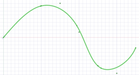
Fit=Trueuses Curve Fitting. Curve Fitting creates a curve that "Fits" the data points using a specified tolerance. The curve may not pass exactly through all points and the distance from the curve to the point will be within the tolerance.Use the
Fittolkeyword whenFit=Trueto specify the Curve Fitting tolerance in model units. For exampleFittol=1.0e-2The curve below uses Curve Fitting (that is, Fit=true). A large tolerance (fittol=2.0) is used to exaggerate the fact that the curve does not pass through the points but only gets within the specified tolerance.
Fit=Falseuses Interpolation. Interpolation requires that the curve pass exactly through all of the points. An interpolation method is used to build a continuous curve through all of the points.The curve below is interpolated (that is,
Fit=False). There are seven points in the file and the curve passes exactly through each one.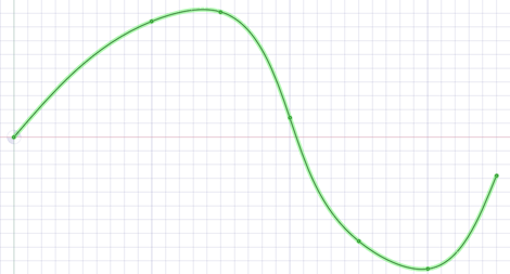
Multiple curves are separated by blank lines.
You can import point curve text files that contain single-point curves, which will be created as points.
Point-curve text files opened or inserted in display a closed curve when the file has a repeated value.
Curves can be imported to coordinate systems or other geometry like other imported objects.
Point-curve text files with columns separated by commas can be opened or inserted. This feature allows you to import any comma-separated value file into .
If there is an error reading the input text file, a message will appear with the line number of the error in parentheses followed by the text appearing on that line.
The following example shows the contents of a point curve text file on the left and the 3D curves it creates on the right:
Note that the point coordinates are (Z, X, Y).
For example (1, 2, 3) is (Z=1, X=2, Y=3).
|
3d=true polyline=false 1 0 0 1 0 1 1 1 0 1 1 1 2 0 1 2 1 0 3 0 0 3 0 1 3 1 0 |

|
Keywords:
-
polyline=false- spline curves are created. -
polyline=true- straight lines are created. -
3d=true- 3D curves are created. -
3d=false- curves are two-dimensional. This is also the case if the option is not set. -
fit=true- use Curve Fitting.- Curve Fitting finds the "Best Fit" through the points.
- Does not require the curve to pass through all of the points
-
fit=false- use Interpolation.- Interpolation forces the curve to pass through all the points in the file.
-
fittol=1.0e-2- Curve Fitting tolerance in the units used in the file.
The blank line after the first set of coordinates indicates that the next set of coordinates is a new curve.
You can copy the file contents above and paste them into a text file, then use  Insert File to try it yourself.
POV-Ray
Not supported
Microsoft® PowerPoint®
Not supported
QIF
V2.0
parts, assemblies
PMI import and export supported
Revit
V2020, V2021, V2022, V2023
.rvt, .rfa
Rhino®
version 4.0, V5.0, V6.0, V7.0
parts, assemblies
.3dm
When importing a Rhino file, multi-segmented curves are consolidated.
You can export layer names, color information, sketch lines, and material information.
Neighboring topology is taken into consideration by default. This means that if problems are found with a face, then its neighboring faces can provide information used to fix the face.
The SpaceClaim plugin for Rhino is only supported for Rhino V5.0.
| Supported Rhino Object | Rhino object | entity |
| Solids | Closed polysurfaces | Solid body |
| Closed surfaces: sphere, torus, ellipsoid dots; | ||
| Polysurfaces (open) | Sheet body | |
| Surfaces | Trimmed surfaces | Sheet body |
| Untrimmed surfaces with boundary edges | ||
| Curves (curve, polycurve) | Named sketch curve | |
| Point objects (point, point cloud) | Not supported | |
| Polygon mesh objects | Not supported | |
| Object name | Entity name | |
| Object color | Entity color | |
| Layers | Layer name | Layer name |
| Layer color | Layer color | |
| On/off layer | Show/hide layer | |
| Locked/unlocked layer | Locked/unlocked layer | |
| Layer structure | Component structure | |
| Materials | Material name | Material name |
| Other material attributes | Not supported | |
| Groups | Not supported | |
RS Components
V2015.0 SP0
parts, assemblies
.rsdoc
rsdocs can only be imported for the first 30 days after SpaceClaim activation. After 30 days, a limit of 100 individual file imports is enforced.
SketchUp®
Up to SketchUp 8, V2013, V2014, V2018, V2019, V2020, V2021
parts, assemblies
.skp
SolidEdge
V18 - 2024
parts, assemblies
.par, psm, .asm
SOLIDWORKS®
SW 98 through SW 2024
parts, assemblies
.sldprt, .sldasm
If you open a SOLIDWORKS file, searches for required assembly and external part files in the following locations:
Root folder of the assembly
Equivalent subfolder in new root folder
Absolute path to the component saved in the assembly file
When you import a design from SOLIDWORKS, the units are changed to match the part.
- Import supports User Defined Attributes for Parts, Assemblies, and Sub-assemblies.
- SpaceClaim supports selective imports from SOLIDWORKS assemblies:
When opening the file:
- Select "SOLIDWORKS" file type.
- Check the "Expand Assemblies" in the file open dialog.
- Select the ".sldasm" file for your configuration.
Select the configuration or sub-assembly to load from the Assembly Browser dialog and click Open.
- The option to import Planes (SpaceClaim Options > Import options > Planes) is not supported when importing a SOLIDWORKS file into SpaceClaim.
STEP
AP203, AP214, AP242 (geometry)
parts, assemblies
.stp, .step
When you import STEP assemblies from one file, select the Create multiple documents when importing assemblies file option if you want the assemblies to remain in one file instead of being split into multiple files, one for each internal component.
- Origin import and export is supported
- PMI import is supported
- License is required
STL
Facets or Solids
parts, assemblies
.stl
When exporting STL files, the output is set to Binary by default.
STL files can include polyface meshes, and they can be imported as lightweight objects. Polyface meshes are imported as solids.
When saving as an .STL file, the quality is based your graphics quality setting. You should set the option to enable the highest possible graphics quality if you want your design to be useful as an SLA rapid prototype for form, fit, and function purposes.
You can import an STL file as a solid, if it has multiple planar areas that can be merged into one planar face.
You can import an STL file as a Mesh object and export it as another STL file. This makes it possible to import multiple STL files into a document and then export everything as a single STL file.
VDA-FS
version 1.0 and 2.0
parts
.vda
Video files
files (insert only) with proper codec(s) required for all but WMV and AVI
.wmv, .avi, .flv, .mkv, .mov, .mp4, .mpg, mpeg, .ogm, .vob
VRML
Facets
parts, assemblies
.wrl
Non-triangular faces are supported.
Wavefront
Facets
parts, assemblies
.obj
XAML
Not supported
XPS
Not supported