


Applying a Limits and Fits Tolerance
-
In the Properties panel, change the Tolerance Type to
Limits and Fits, or click
 in the mini toolbar.
-
Change any of the properties as appropriate.
In the Limits and Fits section of SpaceClaim Options > Detailing, you can set defaults for the properties.
Limits and Fits symbols combine the IT Grade Number and the Fundamental Deviation letter. "IT" is dropped from the Grade Number so only the number is shown. The tolerance size is therefore defined by the Basic Size of the part followed by a symbol containing a letter and a number. A Fit is indicated by the Basic Dimension common to both components, followed by a symbol corresponding to both components with the Internal part symbol preceding the External part symbol.
The table below shows examples.
Option Description Internal (hole) component 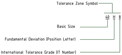
External (shaft) component 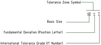
Fit between a hole and shaft with a basic size of 40 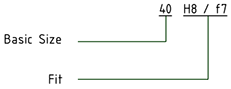
-
Set the Method of Designating property to change the
symbol's display format. The table below illustrates the choices.
Option Description 40H8 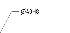
40H8 (40.039/40) 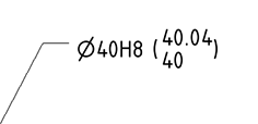
40.039/40 (40H8) 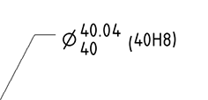
40.039/40 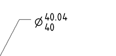
40H8/h7 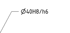
When you change the size of a dimension that has Limits and Fits tolerances, the Upper and Lower Limits will change according to the limits and Fits tolerance tables.
If you modify the IT number, the tolerance symbol updates accordingly.
The dimension color is changed to Red if it has Limits and Fits tolerance and some of the input parameters are invalid. An example is shown below.
Example:
| The tolerance has a Fit for H01/n01 | 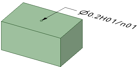 |
| The Fit was changed to H01/a01, which is invalid | 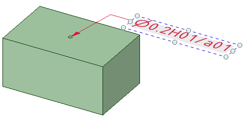 |