


Section Links:
Starting with release 2024 R2, Sherlock automates the process of taking a BGA component from the Parts List and modeling it in greater detail for export to Ansys Mechanical. In short, Sherlock models the BGA as a small, rectangular circuit board, converting the BGA elements to CCA elements. Previously, this kind of modeling had to be done manually. Now Sherlock does much of the work for you. Once the transformation is complete, the new Detailed Component has the following characteristics:
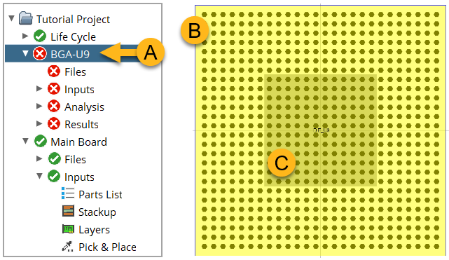
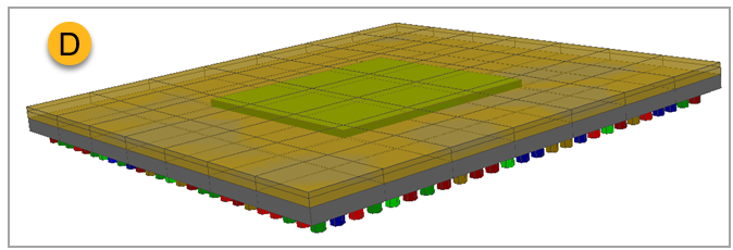
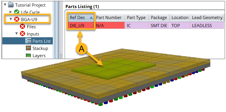
The new Detailed Component appears in the Project Tree as a CCA (A, in the image below). For details on the CCA's properties, see CCA Properties below. Image B shows how the Detailed Component appears in Sherlock's Layer Viewer. In image D, it is shown in the 3D Viewer.
Note: For the purpose of explanation, the instructions in this section use BGA component U9 from the Sherlock tutorial as an example. See Tutorial: Project Overview.
To model the die, Sherlock adds a single leadless part (C, below) centered on the CCA. For details on the CCA's properties, see Die Properties below.
To model the overmolding, Sherlock creates a potting region. The yellow color coding in image B represents the potting. For details on the potting region properties, see Overmold-Potting Region Properties below.
Sherlock creates mount points to model the balls. For details on the mount point properties, see Mount Point - Ball Properties below.
Tip: Remember, the Detailed Component model is intended for export to Ansys Mechanical. Since it is modeled as a PCB, you can export the Detailed Component exactly as you would any other PCB. See FEA- Ansys Workbench Integration .
Tip: Before creating the Detailed Component, verify the BGA part properites are accurate and complete.
There are two ways you can launch the BGA transformation to a Detailed Component.
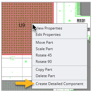
From the Layer Viewer, select Edit Components from the Edit menu. Right-click the BGA component of interest and in the context menu select Created Detailed Component. Sherlock will ask for confirmation before creating the detailed component. In the image below, BGA component U9 has been selected.
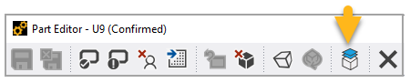
Or, from the Part Editor, click the Create Detailed Component icon shown below. Sherlock will ask for confirmation before creating the detailed component. The icon is active only for BGA components.
Before the CCA creation is initiated, Sherlock may prompt you to provide information if additional part properties are required. In the example of component U9 from the tutorial circuit board, you must specify the following:
Set the Overmold Material to OVERMOLD-BGA (Package tab in the Part Properties Editor).
Enable Potting Usage for the overmold material using the Material Editor.
Specify Ball Count and related properties in the Ball tab. Ball Count = 100. Ball Perimeter Rows = 10. Ball Perimeter Cols = 10.
The sections below explain how Sherlock determines the properties for the Detailed Component which, remember, is modeled as a small CCA. In Sherlock, you can edit the properties of the Detailed Component just as you would any CCA.
Links:
The new detailed BGA component, which appears as a CCA in the Project Tree, will have the following properties:
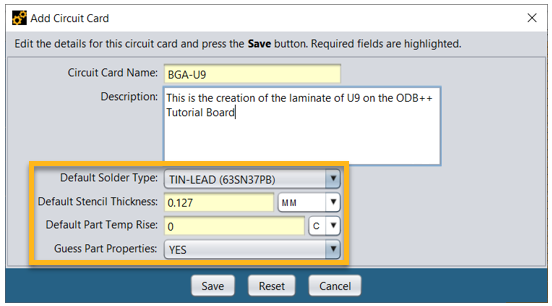
The name of the circuit card will be BGA-<RefDes> (BGA-U9, for example).
The circuit card will include three layers, each 100% Substrate Material.
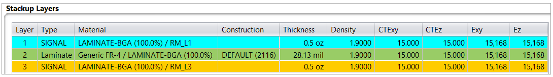
The Default Solder Type, Default Stencil Thickness, Default Part Temp Rise, and Guess Part Properties will be the default values from Sherlock, as shown below.
Other CCA Properties: The shape of the new circuit board will be rectangular with the following properties:
CCA Property of the New Detailed Component Based on the Property of the Original BGA Board Units Package Units Board Length Package Length Board Width Package Width Board Thickness Laminate Thickness Conductor Material Substrate Material Conductor Percentage 100 All other parameters Default Sherlock Parameters
Sherlock creates the overmold as a potting region with the following properties:
| Potting Region Property on the New Detailed Component | Default Value |
| Potting Side | TOP |
| Potting Material | Overmold Material of the orginal BGA component |
| Potting Units | Package Units of the orginal BGA component |
| Potting Thickness | Overmold Thickness of the orginal BGA component |
| Potting Standoff | 0 |
| Potting Region Shape Type | PCB |
To represent the die of the new detailed model, Sherlock creates a part centered on the new CCA (A, below). The name of this part will be Die_<RefDes>. As an example, for BGA U9, the name of the part will be DIE_U9. The Part Type will be IC.
| Package Properties of Component Representing the Die | |
| Package Name | DIE |
| Package Type | DIE |
| Package Mount | SMT |
| Package Units | Die Units from Original BGA |
| Package Length | Die Length from Original BGA |
| Package Width | Die Width from Original BGA |
| Model Part | ENABLED |
| Corner Shape | SQUARE |
| Corner Face | TOP_BOTTOM |
| Material | SILICON |
| Location Properties of Component Representing the Die | |
| Board Side | TOP |
| Location Units | Package Units from original BGA part properties |
| X Coordinate | 0 |
| Y Coordinate | 0 |
| Rotation | 0 |
| Mirrored | N |
| Solder Properties of Component Representing the Die | |
| Solder Model | DIE MODEL |
In the detailed component model, Sherlock creates mount points to represent the balls. The mount points have the following properties:
| Properties of Mount Points (MP) that Represent the Balls | |
| Mount Point ID |
|
| MP Type | Mount Pad |
| MP Units | Based on Ball Units property of original BGA |
| MP Side | Bottom |
| MP Height | Uses Ball Height property of original BGA |
| MP Material | Uses Ball Material property of original BGA |
| MP State | ENABLED |
| Mount Point Shape Properties | |
| Shape Type | Circular |
| Clircle Diameter | The average of the Ball Diameter, Ball Package Diameter, and Ball Pad Diameter. |
| # Nodes | 6 |
| Center X | Netlist or Ball Pattern X Coordinate |
| Center Y | Netlist or Ball Pattern Y Coordinate |
| Rotation | 0 |
The Detailed Component model is intended for export to Ansys Mechanical. Since it is modeled as a PCB, you can export it exactly as you would any other PCB. See FEA- Ansys Workbench Integration for instructions on exporting to Mechanical.
Tip: For tutorials on running an analysis on the Detailed Component in Ansys Mechanical, visit the Ansys Learning Hub.