


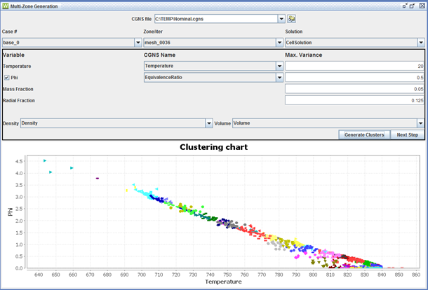
The first step in creating a Multi-Zone HCCI Engine project from a CFD solution is to browse to and select the CFD file that contains the cold-flow simulation results. Next, select which portion of the CFD solution you want to use in the Multi-Zone HCCI Engine model definition. As shown in Figure 2.28: Multi-zone clustering algorithm interface , there are three pull-down menus that allow you to select the portion of the CGNS file of interest. These include "Case #", which is usually just "base0" but may contain other items if more than one entire CFD solution is contained in the file; "Zone/iter" allows selection of the time point or iteration number from the CFD solution; "Solution" indicates what type of solution data to use, such as Cell-centered or Vertex-centered when both exist in the file. For more information about CGNS format, see the CGNS CFD Data Standard from github. The Multizone extraction is capable of reading an Ansys Forte solution file (.ftres) because it also uses CGNS formatting.
After the solution point and mesh region have been selected, the next step is to define the criteria for the cell clustering algorithm that will define the zones in the Multi-Zone HCCI Engine model. The default values for these criteria are automatically populated. Temperature is the main variable of interest, but equivalence ratio (Phi) can additionally be selected.
In order to identify the temperature (or Equivalence Ratio) variables in the CFD solution file, you may need to use the pull-down menu under CGNS Name to select the appropriate variable name used by the CFD code. Otherwise, Reaction Workbench will attempt a simple string match.
In addition to maximum variance values for temperature and, optionally, equivalence ratio, you may modify the default for the maximum mass fraction allowed for each zone (cluster of CFD cells). Maximum fraction of radial extent from the geometry centerline may also be specified to allow geometric location to be considered during the clustering.
Once these criteria have been set, you should verify or select the variable associated with mass density and cell volume in pull-down menus listing CFD variables for these two properties.
At this point the Clustering Chart will display all the CFD cells in the selected solution point on the Phi-T map. This gives you an idea of the stratification of the solution in terms of these variables for the selected time point. Now you can click on the Generate Clusters button to show how the zone-criteria specified will translate into zone definitions. The Generate Clusters operation may take some time, depending on the size of the CFD solution file. Once it is finished, the Clustering Chart will be updated, with each point on the chart representing a CFD cell now colored according to its destination cluster or Zone.
Once you are happy with the cluster definitions, you can click the Next Step button. In the next panel, you will need to specify the initial temperature and density at Intake Valve Closure (IVC) for the engine cycle. This is necessary in order to determine an appropriate mapping of heat-transfer area to zone, even though the zonal model is likely starting later than IVC. The IVC data are used to determine the extent of heat loss that occurred at each zone relative to IVC conditions, which is used to estimate the relationship between the overall surface area and the heat-transfer area for each zone in the Multi-Zone HCCI Engine Model.
After specifying the initial temperature and initial density at IVC, the heat transfer area fraction for each zone are estimated to match the temperature profiles in each zone. The final step for the Extraction utility, then, is to click the Generate Multi-Zone button. This will prompt you for a file location and name for the new Ansys Chemkin project. Once this is specified, the new Chemkin project will automatically be created and the Chemkin Interface is launched. The heat transfer area fraction, mass fraction, temperature, and optionally the equivalence ratio are all populated into each zone in a Chemkin Multi-Zone HCCI Engine model project.
The remaining tasks within the Ansys Chemkin Interface are to:
Select an appropriate detailed-kinetics mechanism and pre-process it in the new project.
Enter the engine settings in the Reactor Properties panel.
Set the global definition of the reactant species or fuel/equivalence ratio settings in the Reactant Species panel. If equivalence ratio was used in the clustering, be sure to use the equivalence ratio option here. Then the zone-specific equivalence ratio extracted from the CFD solution will supersede this value for each zone.
Details on running and post-processing the Multi-Zone HCCI Engine project can be found in the Multi-zone HCCI Engine Simulation tutorial, in the Chemkin Tutorials. The Chemkin Tutorials book is available on the Ansys Help website.