


The folder examples\lsdyna contains a
simple example that simulates the sheet metal forming production process (deep drawing)
of a shell structure. This image shows the process setup:
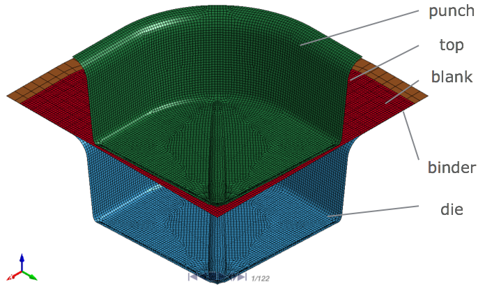
LS-DYNA and LS-PrePost were used to create the numerical model. Due to symmetry of geometry and loading, only a quarter of the structure is modeled. The top is invisible in the figure. During the production process, the punch is subject to vertical motion. Because all bodies except the blank are rigid, the blank is deformed into its desired shape. At the end, the rebound phase is initiated by removing the top and binder and shifting back the punch. The blank rebounds to its final geometry.
The following demo is an animated GIF in the online help. View online if you are reading the PDF version of this guide.
The FEM mesh of the blank contains approximately 10,000 nodes and linear shell elements so that this example can run on even low-end computers. While this simple deep drawing setup is not very realistic, it demonstrates most of the features of oSP3D within a robustness evaluation.
For the blank material, aluminum is chosen using a bilinear plastic material model. optiSLang was used to evaluate the robustness of the structural design. The simulation of the production process was repeated 100 times, using slightly varied input parameters. For a list of input parameters, see:
When evaluating the robustness of the process, engineers are interested in random fields that are distributed on the FEM mesh, including the equivalent plastic strain, thickness reduction (thinning), and FLC (forming limit curve) coefficients.
The simulation is not a real-life example. Its main purpose is to demonstrate most of the functionality of oSP3D as a postprocessor. Simplifying the geometry and process parameters reduces the ability to interpret the data, as shown in Case A: With Eroded Elements.
Unless stated otherwise, the directory paths for Case A and Case B are subdirectories
in examples\lsdyna.