If the optiSLang settings are modified to use the MOP3 node as default, a MOP3 node is created when using the sensitivity or robustness wizard, for example, in the Sensitivity Analysis of a Coupled Function tutorial.
As an alternative, the MOP3 can be manually added to the scenery. This also holds for the case where the classical MOP is still used as default. From the Modules pane, drag a MOP3 node to the Scenery pane and let it drop.
Finally, provide the training data to the MOP3 node using one of the following options:
Load data via File-chooser in the MOP3 settings dialog.
Connect the predecessor (e.g., a Sensitivity System) OMDBPath output slot with the MOP3 IPath input slot
Connect the predecessor (e.g., a Sensitivity System) ODesigns and OParameterManager output slots with the respective IDesigns and IParameterManager input slots.
If an input file is specified and both input slots (IDesigns and IParameterManager) are connected, the data provided by the input slots will be used as training data for the MOP3.
Creating and Connecting a MOP3 Node Example
The following exercise acts as an example for the manual creation and connection of the MOP3 node.
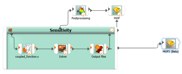
Complete the instructions in the Sensitivity Analysis of a Coupled Function tutorial, up to the end of the Running the Sensitivity Analysis step.
You will end up with a workflow that looks like the following:
From the Modules pane, drag an MOP3 node to the Scenery pane and let it drop.
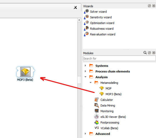
If you do not see this node, ensure you have enabled beta features.
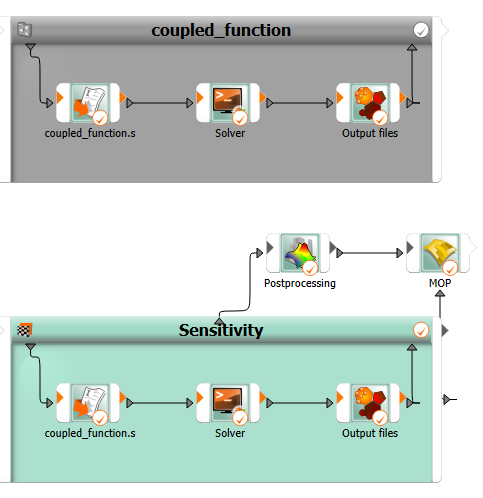
Connect the Sensitivity system's OMDBPath output slot to the MOP3 node's IPath input slot.