


Design validation using the option transfers data to the downstream system's Geometry cell. The benefit of this option is that you can revise the geometry in a CAD application. Follow the steps below to validate your simulation.
Note: As desired, you can use Non-Ansys tools to validate your design. You will need to retrieve the STL file of the optimized design in order to import it into the geometry modeling software of your choice.
Create Validation System
To validate your optimized topology, actions are required in Mechanical as well as Workbench.
File Preparation in Mechanical
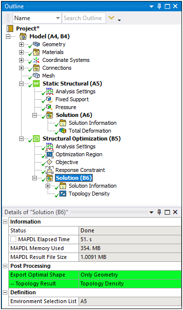
The optimized geometry file - in Standard Tessellation Language (STL) - is created from the selected Topology Density result picked using the --Topology Result property of the Solution object of the optimization system in Mechanical. The --Topology Result property only appears when the property Export Optimal Shape is set to .
By having both geometries available in the Geometry cell (in Workbench), you can perform actions such as overlaying or preserving sections of the geometry or sweep surfaces in order to create additional material around selected regions such as bolt holes.
Note: If you decide to use SpaceClaim to adjust the optimized geometry, check the Additive Manufacturing section (as well as the Designing, Repairing problems, and Preparing designs for analysis sections) in the SpaceClaim Help for the tools you can use to simplify and prepare the optimized geometry in the new system.
Create Design Validation System in Workbench
Once you have specified the desired result to export and solved the analysis, return to Workbench. As shown below, the highlighted context menu option becomes available to transfer the Results cell of your completed analysis to either the Geometry cell or the Model cell of a newly created system. To begin this process, right-click the Structural Optimization's Results cell and select the option from the menu.
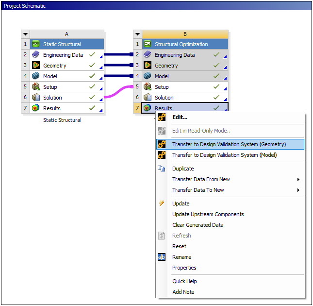
Note: The operation is the same if you have multiple upstream systems.
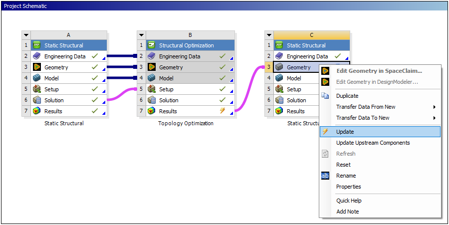
Once you select the option, Workbench creates a new Mechanical system of the same type that is upstream of the optimization system and send the original geometry and the optimized geometry to the Geometry cell of the new system. Next, the Geometry cell of the new system to update the Results cell of the optimization system (which changed to out of date after the new system is created and linked) and the Geometry cell of the new system. The Geometry cell of the new system becomes up-to-date after the action is complete.
If you are working with two upstream systems, you simply need to the first newly created system. All other downstream systems share Engineering Data, Geometry, and Model cell data. Once updated, you can validate all of the systems in one Mechanical session.
Note: Even though the Geometry cell of the new system is up-to-date, first simplify the optimized geometry using SpaceClaim before attempting to open up the geometry in Mechanical. Attempting to open the unsimplified optimized design from the STL file in Mechanical will take a long time and will lead to issues due to the use of facets.