


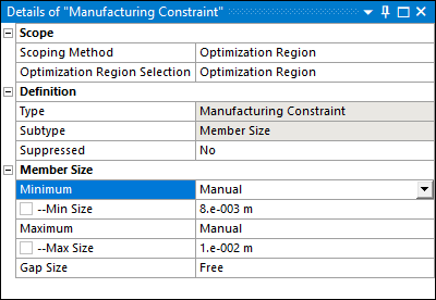
The Minimum property prevents the formation of thin features in the optimized shape.
Industry Motivation
This specification is motivated by several industrial manufacturing processes. Examples include:
During a casting process, you can actively avoid thin areas in the mold that can lead to failure as a result of premature solidification.
During an additive manufacturing process, you can avoid thin members that can result in imperfections in the printing process.
Member Size Minimum Definition
In theory, the computation of the minimum member size is performed in two steps:
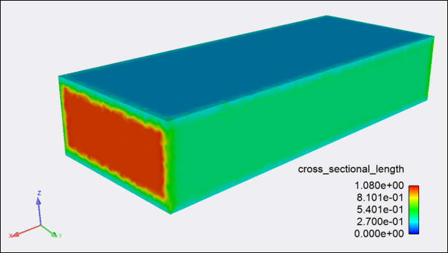
The application computes the cross-sectional thickness for every point on the boundary, that is, the distance until crossing the opposite boundary along the direction opposite to the exterior normal vector.
The minimum value of the distance field is defined as the minimum member size of the structure.
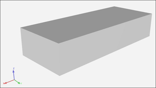
For example, in the wall-type example, the cross-sectional length equals:
Length (X-direction)
Width (Y-direction)
Height (Z-direction)
| Plate Structure | Cross-sectional Length |
|---|---|
 |
 |
This formulation has two main drawbacks:
It is not derivable due to the minimum operator, and therefore not suitable for gradient-based optimization algorithms.
It is not applicable for all methods, namely it requires geometric information that is not available for density-based methods.
The Minimum Member Size constraint is available for density-based optimization, mixable density, and level-set based optimization. The formulation depends on the structural optimization framework.
| Density and Mixable Density | Level-Set |
|---|---|
| Built-in approach based on filtering techniques [2]. | The theoretical definition is adopted, based on the cross-sectional thickness, and is appropriately adjusted to overcome the differentiability issue [13]. |
Setup and Technical Specifications
The setup only requires specifying the lower limit not to violate, denoted
 , in terms of length units.
| Density Based | Mixable Density | Level Set Based | |
|---|---|---|---|
|
|
Note: |
Note: |
|
|
Exclusion Region |
You specify whether to Include or Exclude Exclusions from the Analysis Settings. |
Exclusion regions are inherently considered in the member size evaluation. | |
|
Infeasible Regions[a] |
Naturally ignored | Detected and eliminated from the constraint evaluation. | |
|
Special treatment |
None | The optimization runs first without the MinMS constraint. If
the solution does not meet the requirement, then the optimization continues
adding the MinMS as a constraint. | |
|
Mesh Size |
The finer the mesh, the more accurate the computations related to Minimum member size. | ||


[a] Regions where the Minimum Member Size cannot be respected - closely spaced boundaries.
Recommendations
Note the following:
The computational time for the Minimum Member Size constraint increases together with
and the mesh size refinement.As any constraint, the Minimum Member Size affects the objective performance. Namely, by increasing
, the feasible domain shrinks and probably leads to
smaller objective gain. Especially when an objective function with
antagonistic behavior is used, that is, the volume, this tendency
becomes more significant.
Example
For the following example, the Optimization Type property is set to the option. The optimization problem consists of:
Minimizing the structural compliance under a volume fraction constraint of 0.4.
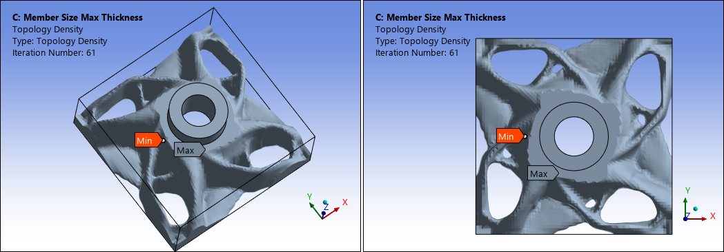
A Maximum Member Size constraint with dmax = 1.0e-02.
A Pull-Out Direction constraint in the Z-direction.
A Cyclic Repetition Design Constraint with 4 sectors enforced.
The upstream Static Structural system is specified with two displacements, a force, and a moment, as illustrated.
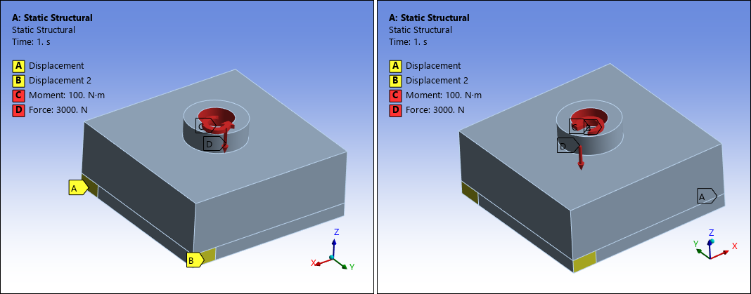
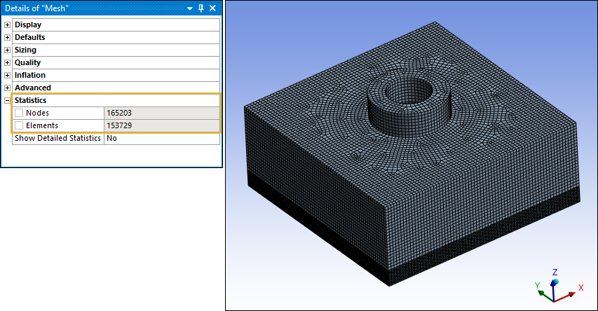
The finite element mesh includes 153,729 elements.
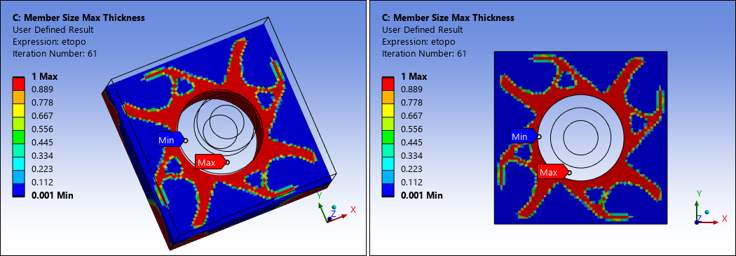
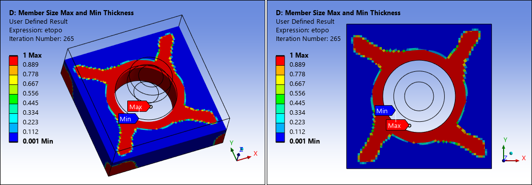
As shown from the Topology Density as well as a User Defined Result, the optimized result without considering an minimum member size constraint, shown here, produces slender "ribs.". Note that the User Defined Result shown below is a cutout of the result using the Section Plane feature.
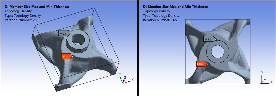
When you add a minimum member size constraint with dmin = 8.0e-03, it leads to the optimized shape where slender ribs disappear.
References
[3] M.P. Bendsoe, O. Sigmund. Topology optimization: theory, methods, and applications, Springer Science & Business Media, 2003.
[13] G. Allaire, F. Jouve, G. Michailidis, Thickness control in structural optimization via a level set method, Structural and Multidisciplinary Optimization, 2016.