


The FRF Worksheet is comprised of 2 or 3 tables depending on the presence of UNV Data.
FRF Frequency Table
The first table in the FRF Worksheet is used to control the modal parameters employed in the FRF Calculation:
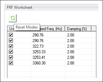
The table is populated with the modes from the analysis. If a given mode is selected/cleared, it will be used/not used in the subsequent FRF Calculation. This action can also be triggered by selecting several rows in the table and selecting the action.
Damping can be tailored for each mode by modifying the value in the damping column. For undamped analyses, damping is 2% by default for all modes. For damped analyses, damping is automatically populated according to the value used in the analysis, and it cannot be modified.
Note: For models that exhibit symmetries that cause mode pairs (for example, models with cylindrical symmetry where bending modes are paired), damping should be changed consistently for all paired modes. This ensures that the symmetry of the model is correctly applied to the FRF calculation.
FRF DOF Pairs Table (Computational Model)
The second table in the worksheet is used to control the DOF pairs to be calculated. The table is initially empty. There are six RMB actions:
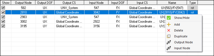
- Show/Hide
If the DOF pair is selected/cleared, it is displayed/not displayed in the FRF Plotter. This action supports multi-selection (if several rows are selected, and the action is selected, all rows are shown/hidden).
- Add
Add a new DOF pair to the table. This action does not support multi-selection.
- Delete
Delete all the selected rows from the table. This action supports multi-selection (if several rows are selected, and the action is selected, all rows are removed).
- Duplicate
Duplicate all the selected rows from the table. This action supports multi-selection (if several rows are selected, and the action is selected, all rows are duplicated at the end of the table).
- Output Node
Sort worksheet data based on output node IDs. You can toggle between ascending and descending sort order by clicking the option again. If the Output Node ID is same in any two or more rows, the data is sorted based on the following order of preference - Input Node ID, Output DOF and Input DOF.
- Input Node
Sort worksheet data based on input node IDs. You can toggle between ascending and descending sort order by clicking the option again. If the Input Node ID is same in any two or more rows, the data is sorted based on the following order of preference - Output Node ID, Input DOF and Output DOF.
Each column in the table can be edited in a different way:
- Output Node/Input Node
The contents of these columns are modified through scoping a node from the mesh. If a cell is clicked, the Geometry view enters Mesh Node selection mode, allowing you to scope nodes. A set of controls appear at the top of the table allowing you to or the selection. Only one node can be scoped. In addition, the input and output nodes can be selected from the dropdown menu.

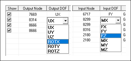
- Output DOF/Input DOF
The contents of these columns are modified through a dropdown menu inside the cell that is populated with all the applicable DOFs for the given node. For the Output DOF, the format of the selection explicitly indicates Displacement (UX, UY, UZ) and Rotation (ROTX, ROTY, ROTZ). For the Input DOF, the format of the selection explicitly indicates Force (FX, FY, FZ) and Torque (MX, MY, MZ).
- Output Coordinate System (CS)/Input Coordinate System (CS)
The contents of these columns are modified through dropdown menus inside the cells that are populated with all the active coordinates systems in the model. By default, the is used. The Output/Input Node IDs and Local Coordinate System triads are displayed in the Geometry view after changing the CS or Node.
- Scalar Load
The contents of this column are modified by entering a scalar value. This value will scale the output FRF. The column is not available when the option in the FRF Plotter is enabled.
- Name
The contents of this column are modified by entering text and modifying the predefined Name. The predefined Name is a mnemonic comprised of the Output and Input DOFs and Node IDs.
- Type
Read-only property, containing information about the origin of the FRF.
The second table has four additional actions that can be accessed through the buttons displayed at the top:
- Export Worksheet to Excel
Exports the worksheet contents to an Excel file.
- Import Worksheet from Excel
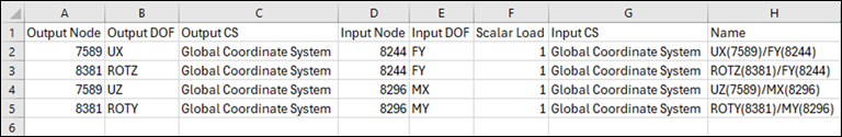
Imports worksheet contents from an Excel file. This Excel file should have the following format:
The FRF contents should be available in the first sheet of the workbook.
The file should have 8 columns, starting at cell A1. The columns must be in the same order as the FRF Worksheet (Output Node, Output DOF, Output CS, Input Node, Input DOF, Scalar Load, Input CS and Name). Type does not need to be specified.
Row 1 is reserved for headers.
- Expand/Contract Worksheet columns
This option shows/hides the Coordinate System (CS) and Type columns from the FRF worksheet.
- Open the FRF Comparison Pane
Opens the FRF Comparison Plotter.
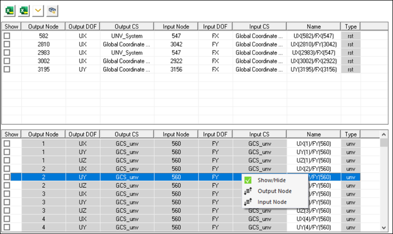
FRF DOF Pairs Table (UNV Model)
The third table in the worksheet is used to control the FRF pairs contained in the UNV file. It is only displayed if the Include UNV Data Property is set to Yes in the Details view. The table is automatically populated when the file is parsed, and it has the same structure as the table at the top.
The FRFs defined in the UNV file cannot be modified, and therefore all columns are read only with the exception of the Name. This third table supports three RMB actions (, and ), which are used in the same way as described for the previous table. When the third table is displayed, an additional button is shown above the second table to show/hide the UNV Node Numbers in the Geometry view. The Input and Output CS that define the DOFs employed in the UNV FRFs are read from the UNV file if Dataset 2420 is available (see UNV File Restrictions), and imported into Mechanical. These CS are read only and should not be suppressed or eliminated. When a given Model transformation is performed (either by another CS, by a RB Transformation or by the Alignment of 3 Nodes), the CS are also changed to match the model update. If the UNV file does not have any dataset, the generic GCS_unv CS is employed.