


The first table in the Pre-Test Worksheet is used to control the modes used in the Pre-Test Calculator:
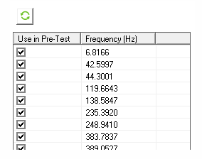
The table is populated with the modes from the analysis. If a given mode is selected/cleared, it will be used/ignored in the subsequent Sensor and Exciter Identification. This action can also be triggered by selecting several rows in the table and applying the right-click action.
The second and third tables in the worksheet are used to control the local Coordinate System at each sensor and exciter location. Both tables are initially empty and have the following right-click actions:
- Show/Hide
If a sensor or exciter is selected/cleared, it is displayed/hidden in the Geometry view. This action supports multi-selection (if several rows are selected, the / action is applied to all selected rows). Additionally, the AutoMAC Table is updated dynamically, considering only sensors selected in the second table.
- Add
This action is only available for the second table (Sensors Table). It allows you to add sensors to the analysis after selecting nodes in the Geometry view (only selection of nodes is allowed). The AutoMAC Table is also updated once this action is completed.
You can also add sensors before the analysis.
In the Sensors Table, the Method used to find the sensor is shown in the last column.
In addition to the tables, there is a Details view at the top of the third table that has the following properties:
- Number of Exciters
Integer property that changes the number of exciters that are considered. Changing this value triggers a dynamic update of the Pre-Test Worksheet plot.
- Exciter and Sensor Icon Scale Factor
Scale factor property that controls the size of exciter and sensor icons (arrows and spheres).
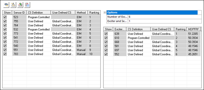
Each column in the table contains the following information:
- CS Definition
Similar to the Coordinate System Definition Properties for sensor and exciter definition, this property allows you to switch between and , and in this case it only affects the individual sensor or exciter that is modified.
- User Defined CS
Similar to the User Defined CS Properties for sensor and exciter definition, this property allows you to scope a previously defined Coordinate System to an individual sensor or exciter. It is only available if the CS Definition at the given row is scoped to .
- Ranking
Read-only column that shows the order of the sensors/exciters according to their algorithm (EIM/MDPFRF). Sensors and exciters in the table are sorted based on this value.
The Sensor table has one additional column:
- Method
Read-only column that indicates the method used for sensor selection. stands for Effective Independence Method, while refers to the user-defined sensors.
The Exciter table also has one additional column:
- MDPFRF
Read-only column that indicates the value of the Maximum Driving Point Frequency Response Function, calculated according to the Exciter Identification Method.
The second and third tables have four additional actions that can be accessed through the buttons displayed at the top:
- Display sensor/exciter IDs
Shows the sensor/exciter IDs in the Geometry view, allowing for easier identification.
- Analyze Sensor Mass Effect
Click this button to start the Sensor Mass Effect Analysis workflow.
- Create Named Selections for Sensors and Exciters
Allows the creation of a Named Selection for selected sensors and exciters.
- Export to UNV file
Allows the export of selected sensor and exciter information in unv format after each generation of the Pre-Test Calculator. _sensors and _exciters suffixes are added to the chosen filename.