


The far sound pressure field and far-field parameters (for example, radiation patterns, directivity, radiated power, radiation efficiency, and target strength) are essential for sound radiation or sound scattering analysis. The equivalent source surface principle using Green’s function allows us to evaluate these parameters.
The surface equivalence principle enables you to calculate the pressure fields beyond the FEA domain. It states that the pressure field exterior to a given surface can be exactly represented by an equivalent source placed on that surface and allowed to radiate into the region external to that surface. Refer to Far Sound Pressure Field and Far-Field Parameters topic in the Mechanical APDL Acoustic Analysis Guide for more information.
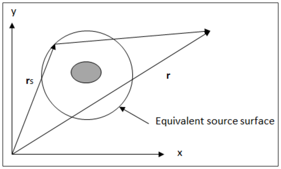
Where:
| r = far-field observation position. |
| rs = equivalent source position on the enclosed surface. |
The following Far-field results are available in Mechanical:
| Polar Plot Results | Microphone Results |
|---|---|
|
|
|
See the Results and Result Tools (Group) object reference page for additional information about the Details view properties for these results.
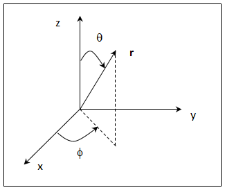
Polar Plot Results
Polar plot results enable you to evaluate acoustic quantities on a spherical arc or surface defined by phi (from x to y), theta (from z to x-y plane), and r (radius) as illustrated in the following global polar coordinate system. You enter these values. In addition, these values are located outside the model mesh.
The arc or spherical surface on which the application calculates the results is displayed in the Geometry window prior to result generation.
Microphone Results
Microphone results enable you to evaluate acoustic quantities outside of the mesh by defining coordinates corresponding to the microphone location. Using the properties of the result object, you define either a singular microphone location in the Details view or up to nine microphone locations using the Worksheet.
Notes
Important: If your Harmonic Acoustics analysis specifies an Incident Wave Source excitation:
The Far-field Sound Power Level and Far-field Directivity results are not supported when the Incident Wave Location property is set to (default).
In order to post process the Far-field Sound Power Level and Far-field Directivity results, the Scattering Field Formulation property must be set to . Refer to the Scattering Controls section for additional information.
The Far-field Maximum Scattered Pressure and Far-field Target Strength results are not supported when the Incident Wave Location property is set to .
Note:
Currently, Far-field results are not:
Supported for animation.
Supported for user Defined Results.
Calculated at points on the finite element model. The Geometry window legend displays the minimum and maximum values but no contours are displayed on the elements.
Except for the Sound Power Level Far-field and Microphone results, all Far-field Results are evaluated for a single frequency or a single set specified by the user. If a specified frequency is not contained in the result file frequency history, then the nearest frequency from the file is used.
The Far-field Sound Power Level and Microphone results evaluate at all frequencies and the minimum and maximum displayed in the Geometry window legend represent the extremes over all frequencies.
When you specify the Model Type property as either or , the location of microphone results is projected onto X-Y plane.
The following capabilities are disabled if you have imported or restored an archive file (that does not include a result file).
Exporting Far-field Results to an ASCII file.
The Worksheet and Tabular Data upon clicking a Far-field Result.
Re-solve the project in order to restore these post processing capabilities.