


The area selected for the fringe plot will be treated as a result only (results will be reported for the nodes on the scoped body). No boundary conditions will be applied.
Analysis Types
Fringe Plot is an Acoustics Load that is available for LS_DYNA Acoustics analyses only.
Common Characteristics
This section describes the characteristics of the boundary condition, including the application requirements, support limitations, and loading definitions and values.
Dimensional Types
3D Simulation: Supported.
2D Simulation: Not Supported.
Boundary Condition Application
To apply a Fringe Plot:
On the Environment Context tab: select > Fringe Plot. Or, right-click the Environment tree object or click in the Geometry window and select > > Fringe Plot.
Define the Scoping Method.
Details View Properties
The selections available in the Details view are described below.
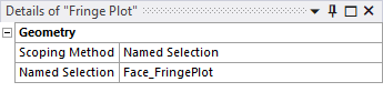
Scope the object using Geometry Selection or Named Selection Scoping Methods.