VM-LSDYNA-SOLVE-033
VM-LSDYNA-SOLVE-033
Combined Bending and Torsion of Beam
Overview
| Reference: | Timoshenko, S. (1955). Strength of material, Part I: Elementary theory and problems (3rd ed.). D. Van Nostrand Co. p.299, problem 2. |
| Analysis Type(s): | Static Structural Analysis |
| Element Type(s): | Beam |
| Input Files: | Link to Input Files Download Page |
Test Case
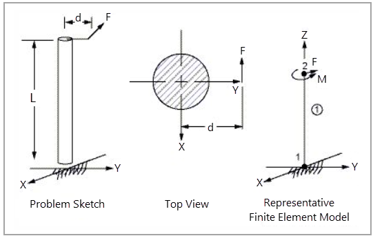
As shown in Figure 120, a vertical bar of length L and radius r is subjected to the action of a horizontal force F acting at distance d from the axis of the bar. Determine the maximum principal stress σmax.
This test case also appears in the Workbench Verification Manual. See VM-WB-MECH-049.
| Material Properties | Geometric Properties | Loading |
|---|---|---|
|
E = 3e7 psi ν = 0.3 ρ = 0.0007345 lbf·s2/in |
L = 300 in r = 2.33508 in d = 3 ft |
F = 250 lb (Y direction) M = 9000 lbf-in (Z direction) |
Analysis Assumptions and Modeling Notes
When setting boundary conditions, keyword BOUNDARY_SPC_SET is used to restrict the movements and rotations of the node at the ends of the beam (node 1) in the X, Y, and Z directions.
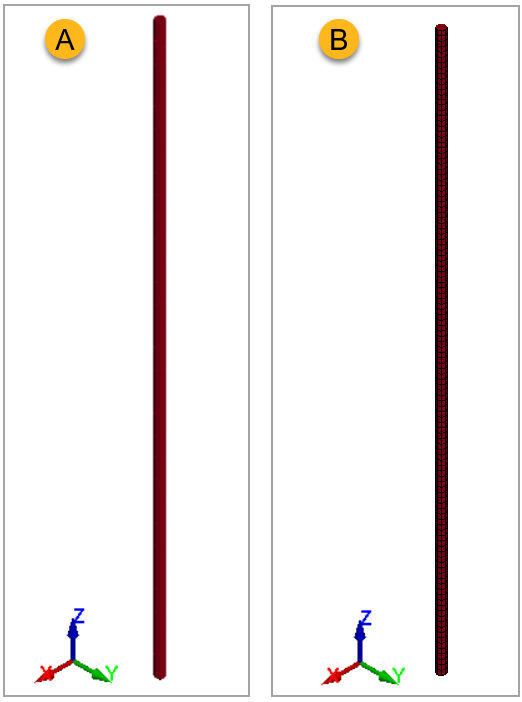
In LS-DYNA, a beam-type model, using the SECTION_BEAM keyword, is used by selecting the section type, with a value for ELFORM of 1 (using the Hughes-Liu formulation with cross-section integration) and a value for QR/IRID of 2 (2 x 2 Gauss quadrature). Figure 121 shows the mesh model (B).