


*CONSTRAINED_NODAL_RIGID_BODY
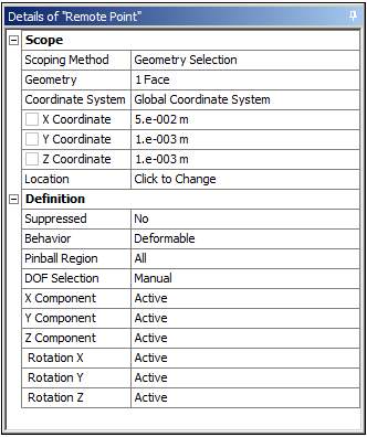
This keyword is generated for remote points. Remote points are a way of abstracting a connection to a solid model, be it a vertex, edge, face, body, or node, to a point in space (specified by Location).
Remote Points are akin to the various remote loads available in the Mechanical application. Remote boundary conditions create remote points in space behind the scenes, or internally, whereas the Remote Point objects define a specific point in space only. A Remote Point is converted to a rigid constraint (nodal rigid body) independent of the stiffness behavior.
the location set in the Remote Point Scope is not used in the input file definition.
Card1
PID = ID of the Rigid Body. It is set in the LS-DYNA solver and does not reflect the ID specified in the remote point definition.
NSID identifies a set of nodes that are to be defined as a rigid body. This set of nodes is based on the scoped entities. The set consists of nodes from several different deformable parts.
PNODE = 0. This is not used in the exported file.
DRFLAG = The value is calculated from the translational active degrees of freedom when the DOF Selection in the Remote Point definition is set to Manual. It allows you to deactivate certain degrees of freedom in the rigid body definition. DRFLAG =
1, when X Component is inactive.
2, when Y Component is inactive.
3, When Z Component is inactive.
4, when X and Y Component are inactive.
5, when Y and Z Component are inactive.
6, when Z and X Component are inactive.
7, when X, Y, and Z Components are inactive.
RRFLAG = The value calculated from the rotational active degrees of freedom when the DOF Selection in the Remote Point Definition is set to Manual. It allows you to deactivate certain degrees of freedom in the rigid body definition. RRFLAG =
1, when Rotation X is inactive.
2, when Rotation Y is inactive.
3, when Rotation Z is inactive.
4, when Rotation X and Y are inactive.
5, when Rotation Y and Z are inactive.
6, when Rotation Z and X are inactive.
7, when Rotation X, Y, and Z are inactive.
*CONSTRAINED_NODAL_RIGID_BODY_INERTIA
This keyword is generated for point masses. Point masses use a remote point for their definition, or can be applied on a remote point. See *CONSTRAINED_NODAL_RIGID_BODY for additional information.
Card1
PID = ID of the Rigid Body. It is set in the LS-DYNA solver and does not reflect the ID specified in the remote point/Point Mass definition.
NSID identifies a set of nodes that are to be defined as a rigid body. This set of nodes is based on the scoped entities. The set consists of nodes from several different deformable parts.
PNODE = 0. This is not used in the exported file.
DRFLAG = 0. All Translational degrees of freedom are active in the rigid body definition.
RRFLAG = 0. All Rotational degrees of freedom are active in the rigid body definition.
Card2
XC = X Coordinate from the Scope of the Point Mass object.
YC = Y Coordinate from the Scope of the Point Mass object.
ZC = Z Coordinate from the Scope of the Point Mass object.
TM = Mass from the Scope of the Point Mass object.
Card3
IXX = Mass Moment Of Inertia X from the Definition of the Point Mass object.
IXY = 0
IXZ = 0
IYY = Mass Moment Of Inertia Y from the Definition of the Point Mass object.
IYZ = 0
IZZ = Mass Moment Of Inertia Z from the Definition of the Point Mass object.